Check patentability & draft patents in minutes with Patsnap Eureka AI!

Rotational Push Switch

a push switch and rotating technology, applied in the field of switches, can solve the problems of difficult for users to visually recognize inconvenient for users in practical applications, and difficulty in recognizing the on/off state of the push switch, and achieve the effect of easy recognition

Pending Publication Date: 2022-02-17
JOEMEX ELECTRIC PROD (DONGGUAN) CO LTD
View PDF0 Cites 0 Cited by
  • Summary
  • Abstract
  • Description
  • Claims
  • Application Information

AI Technical Summary

Benefits of technology

The present invention provides a rotational push switch that is easy to recognize. The switch can be easily switched between ON and OFF states by repeatedly pressing the cap. When the switch is in the ON / OFF state, the symbols can be rotated to align with the display window, making it quick and easy for the user to see the status of the switch.

Problems solved by technology

However, it is difficult to recognize ON / OFF states of the push switches according to outward appearances of the push switches.
Although heights of the switch portions of the push switches will be changed according to whether the push switches have been pressed or not, the heights of the switch portions are changed quite slightly, which is difficult for the user to visually recognize the ON / OFF states of the push switches.
Therefore, it is still quite inconvenient for the user in terms of practical applications.

Method used


Image

  • Rotational Push Switch
  • Rotational Push Switch
  • Rotational Push Switch

Examples


Embodiment Construction

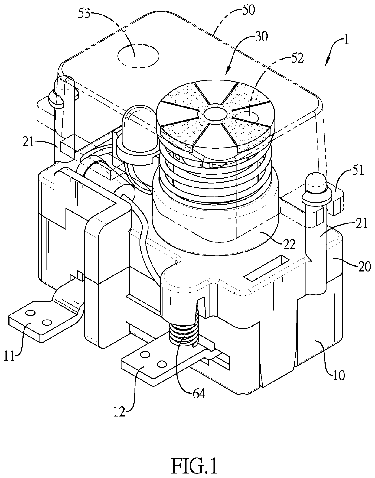
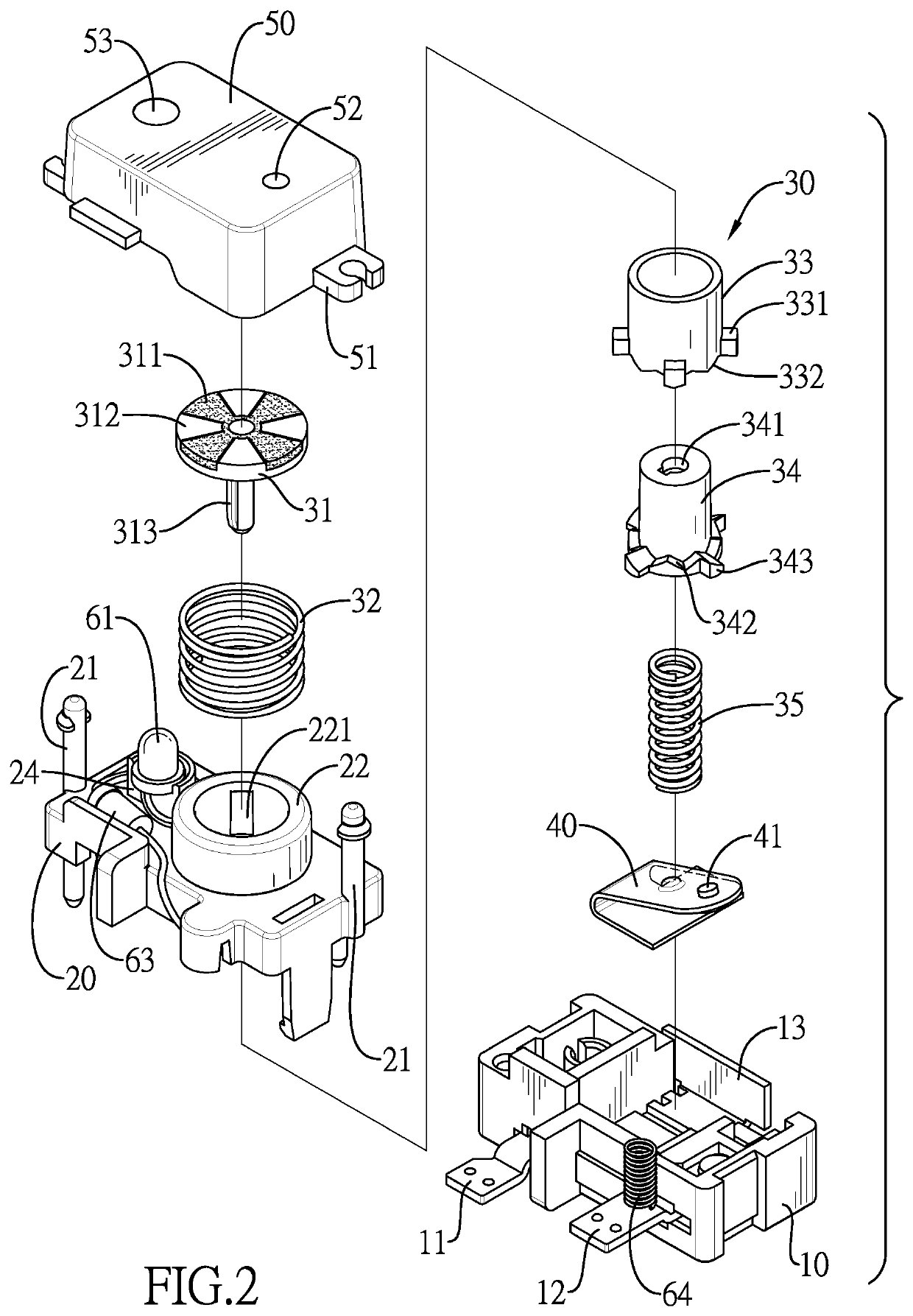
[0026]With reference to FIG. 1 and FIG. 2, the present invention is a rotational push switch 1, and the rotational push switch 1 includes a bottom shell 10, a top shell 20, a switch assembly 30, a conductive elastic piece 40, and a cap 50.

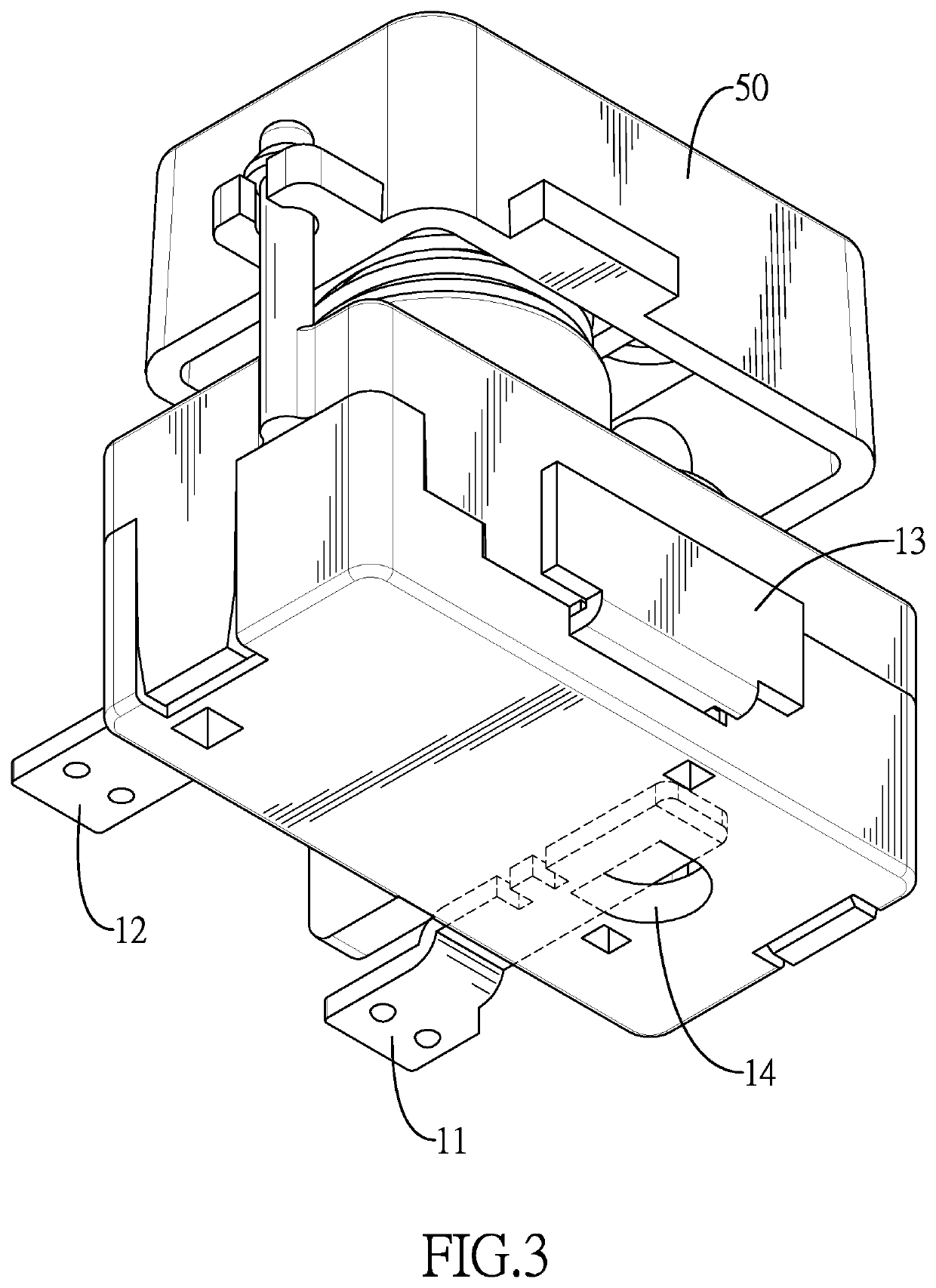
[0027]The bottom shell 10 and the top shell 20 are engaged to form a complete shell. The bottom shell 10 includes a first conductive terminal 11, a second conductive terminal 12, and a third conductive terminal 13. One end of the first conductive terminal 11 is mounted inside the bottom shell 10, and another end of the first conductive terminal 11 extends outward from a front side of the bottom shell 10. One end of the second conductive terminal 12 is mounted inside the bottom shell 10, and another end of the second conductive terminal 12 extends outward from the front side of the bottom shell 10. The end of the second conductive terminal 12 inside the bottom shell 10 forms a lower contact 121. With reference to FIG. 3, the third conductive termina...


PUM


Abstract

A rotational push switch includes a bottom shell having a first and a second conductive terminals connected to a power supply, and a third conductive terminal connected to the conductive elastic piece. The conductive elastic piece is mounted in the bottom shell. A switch assembly is mounted on a top shell mounted on the bottom shell. The switch assembly is switched to connect or detach the conductive elastic piece and the second conductive terminal. A cap is mounted on the switch assembly. When the conductive elastic piece is connected to or departed from the second conductive terminal, ON / OFF symbols can be correspondingly seen in a display window of the cap, and a user can recognize an ON / OFF state of the rotational push switch.

Description

BACKGROUND OF THE INVENTION1. Field of the Invention[0001]The present invention relates to a switch, and more particularly to a rotational push switch for controlling transmission of electric power or signals.2. Description of the Related Art[0002]Push switches are widely used in various fields. For example, the push switches are usually used in electronic products, tools, vehicles, or industrial equipment, and the push switches can control a transmission circuit of an electric power or a signal. The push switch can be alternately switched between an ON state and an OFF state by pressing a switch portion of the push switch. However, it is difficult to recognize ON / OFF states of the push switches according to outward appearances of the push switches. Although heights of the switch portions of the push switches will be changed according to whether the push switches have been pressed or not, the heights of the switch portions are changed quite slightly, which is difficult for the user ...

Claims


Application Information

Patent Timeline
Patent Type & Authority Applications(United States)
IPC IPC(8): H01H19/36H01H19/14H01H19/04
CPCH01H19/36H01H19/14H01H2235/00H01H2221/01H01H19/04H01H13/58H01H19/11
Inventor HUANG, ALBERT
Owner JOEMEX ELECTRIC PROD (DONGGUAN) CO LTD
Features
  • R&D
  • Intellectual Property
  • Life Sciences
  • Materials
  • Tech Scout
  • Unparalleled Data Quality
  • Higher Quality Content
  • 60% Fewer Hallucinations
Learn More