Toothbrush handle

Inactive Publication Date: 2001-12-25
PROULX GENEVIEVE C
View PDF13 Cites 101 Cited by
  • Summary
  • Abstract
  • Description
  • Claims
  • Application Information

AI Technical Summary

Benefits of technology

A principle object of the present invention is to provide a toothbrush handle that normally will be grip

Problems solved by technology

One problem, common to many, is that too much pressure is applied to the teeth and gums during brushing.
Too much pressure can cause, or contribute to, all kinds of dental problems such as recession, abrasion, loss of periodontal ligaments and/or loss of cementum and bone.
Once the roots are exposed the teeth can become sensitive and the exposed roots are vulnerable to root decay.
Tooth brushes presently on the market are available with soft or ultra soft bristles, but this does little to alleviate the foregoing problems because the handle designs are conducive to applying heavy pressure during brushing.
As mentione

Method used


Image

  • Toothbrush handle
  • Toothbrush handle

Examples


Embodiment Construction

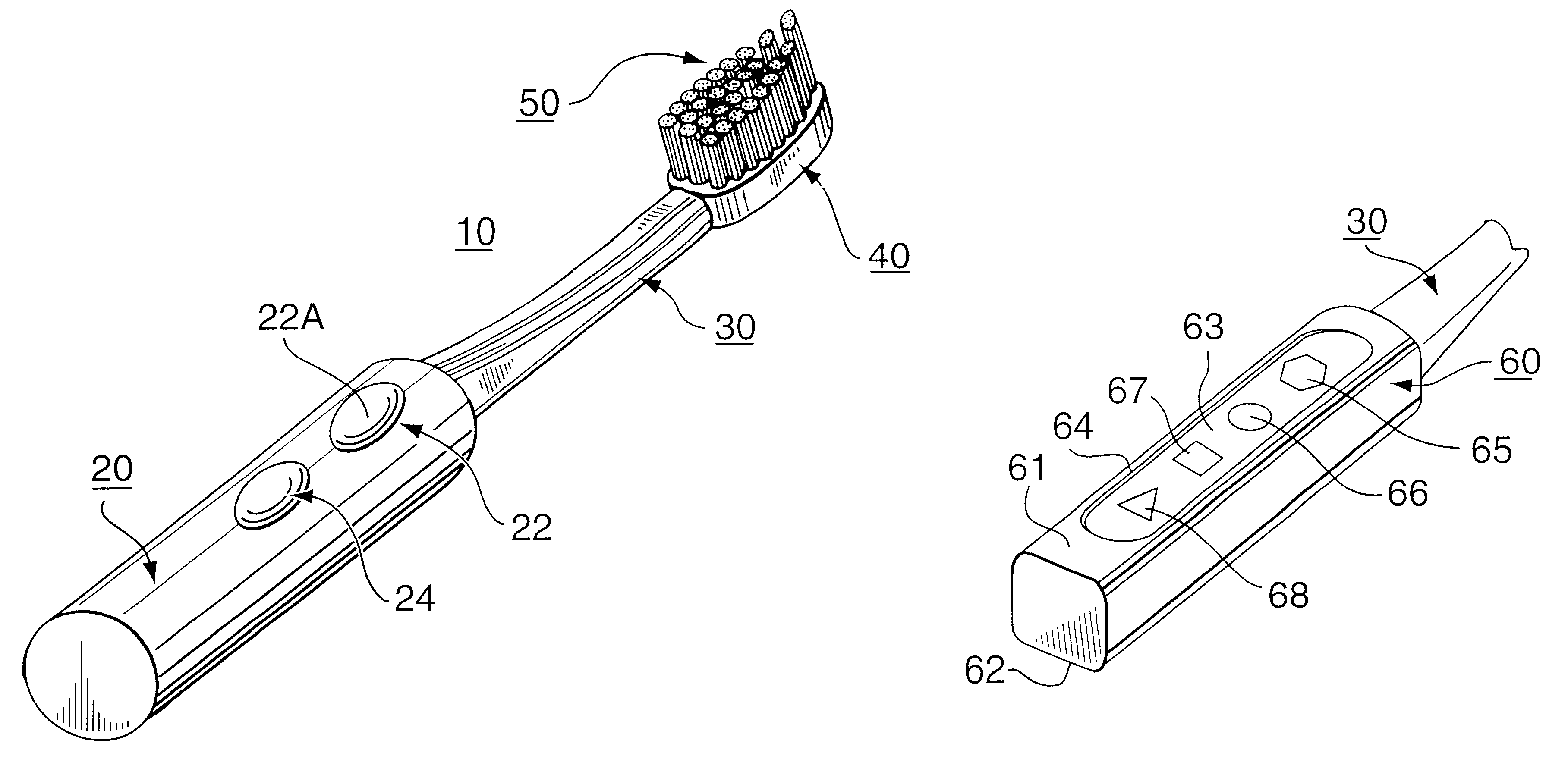
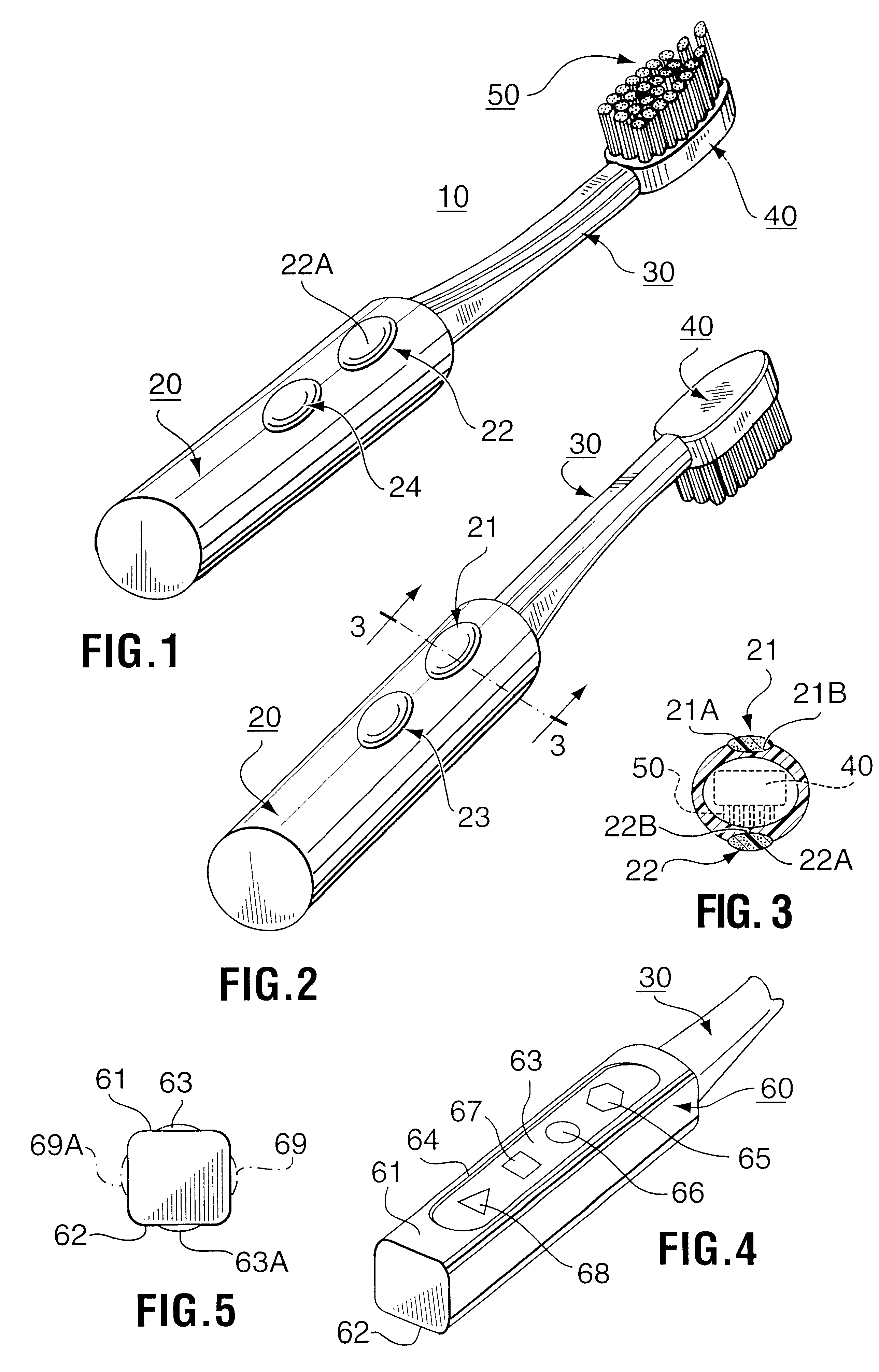
Referring to the drawing, there is illustrated a toothbrush 10 comprising a handle 20, a stem 30, a head 40 and bristles 50. The bristles 50 project outwardly from the head and both the head and the bristles are of conventional construction. For discussion purposes, the face of the handle corresponding to the bristle side of the brush is considered the bottom face (i.e. FIG. 1) and the other (i.e. FIG. 2) the top face.

The stem 30 is slender and conventionally, for the average toothbrush, is approximately 4 to 5 cm in length.

In the present invention, the handle 20 is approximately the same length as the stem.

The handle 20, in accordance with the present invention, has at least an index finger tip engagable area defined on each of the respective top and bottom faces of the handle. The toothbrush handle 20 is larger in cross-sectional outline than the stem 30 and may be circular, oval or rectangular. It is sufficiently large in cross-section so that the toothbrush can be firmly and com...


PUM


Abstract

A toothbrush handle with defined resilient finger tip engagable areas on each of respective opposite top and bottom faces of the handle.

Description

This invention relates generally to dental hygiene and more particularly to a toothbrush handle that contributes to improved dental hygiene and a toothbrush incorporating such handle.This application is closely related to applicant's corresponding Canadian application Serial No. 2,261,355 filed Feb. 10, 1999.The term "dental hygiene", as contemplated herein, concerns healthy teeth and healthy peridontium the latter of which pertains to gums, periodontal ligament, alveolar bone and cementum.In order to maintain healthy teeth and peridontium one needs to be diligent with their home care and practice good dental brushing habits. Extending tooth life is necessary because of increased life expectancy.BACKGROUND OF INVENTIONPeople, with their natural teeth, normally brush regularly to maintain healthy teeth and gums. There are two principle aspects to consider one being the pressure applied to the teeth and the other the motion imparted to the brush during brushing. Both of these aspects ...

Claims


Application Information

Patent Timeline
IPC IPC(8): A46B5/00A46B5/02
CPCA46B5/02A46B5/026Y10T16/498Y10T16/476A46B2200/1066
Inventor PROULX, GENEVIEVE C.
Owner PROULX GENEVIEVE C
Why Eureka
Try Eureka