Check patentability & draft patents in minutes with Patsnap Eureka AI!

Cassette for thermal transfer ribbon for setting images on printing plates

a technology of thermal transfer ribbon and printed plate, which is applied in the field of cassettes for thermal transfer ribbon, can solve the problems of limited ribbon speed, easy wear of ribbon, and damage to functional layers,

Inactive Publication Date: 2003-07-01
MANROLANAD AG
View PDF21 Cites 1 Cited by
  • Summary
  • Abstract
  • Description
  • Claims
  • Application Information

AI Technical Summary

Benefits of technology

The solution allows for high-speed ribbon transport without wear or damage, enabling efficient and automated thermal transfer processes, reducing production costs by eliminating the need for guide rollers and bearings, and allowing for reuse of wear-free components.

Problems solved by technology

In such cassettes friction occurs between the transfer ribbon and guide parts, so that only limited ribbon speeds are possible and the ribbon wears easily or the functional layer is damaged.

Method used


Image

  • Cassette for thermal transfer ribbon for setting images on printing plates
  • Cassette for thermal transfer ribbon for setting images on printing plates
  • Cassette for thermal transfer ribbon for setting images on printing plates

Examples


Embodiment Construction

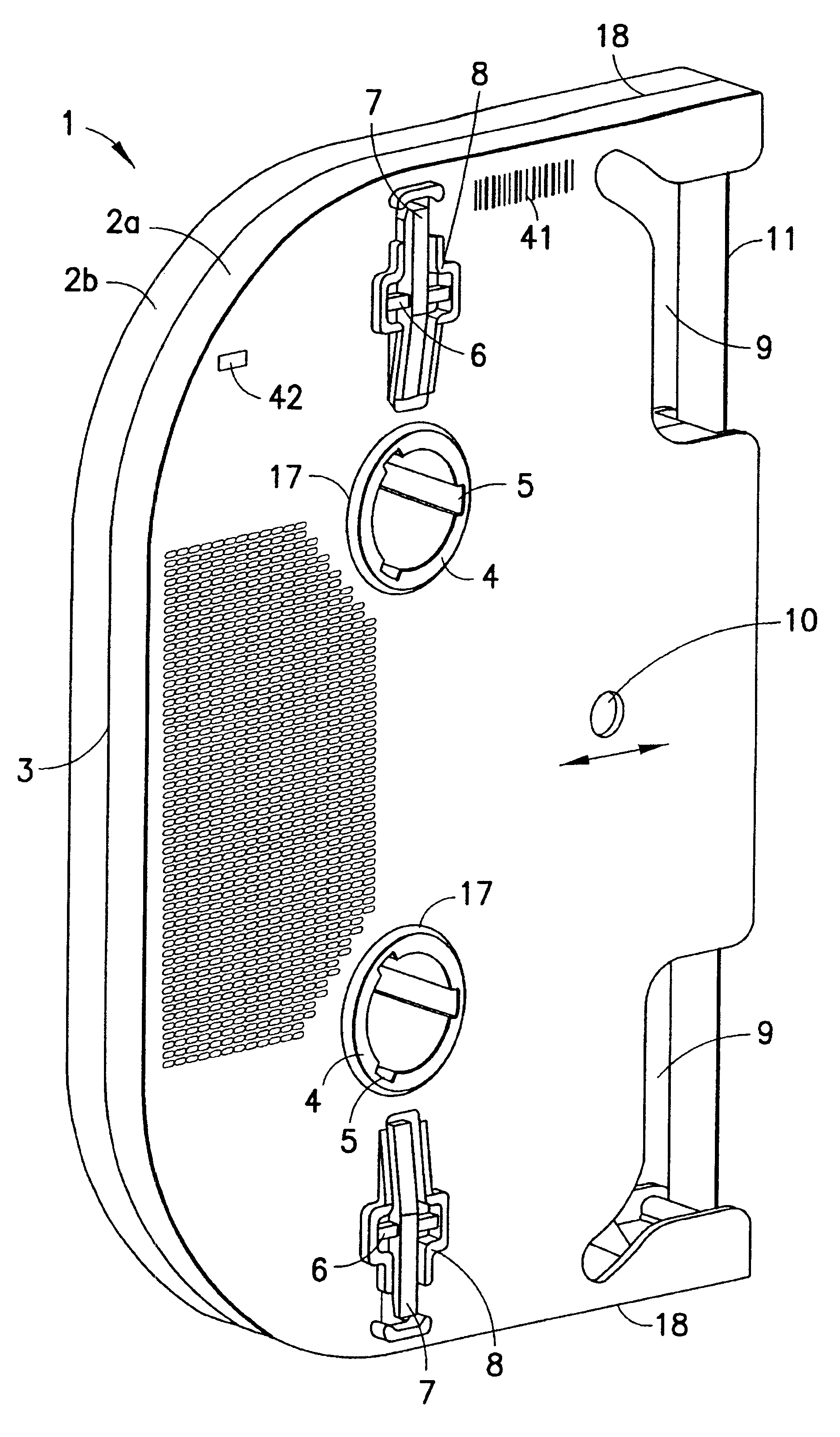
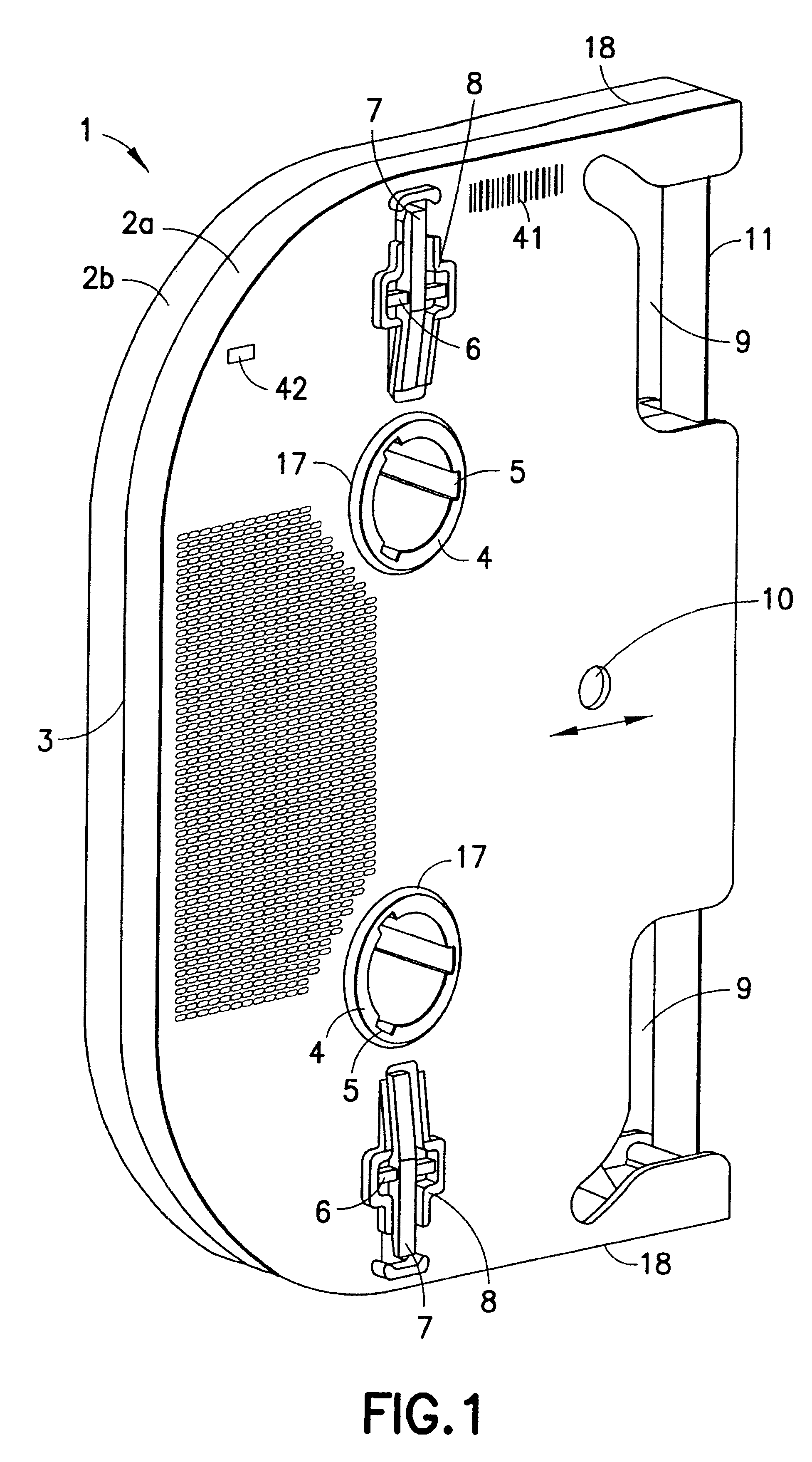
FIG. 1 shows an embodiment of the cassette 1 of the invention in the alignment in which it is inserted into a ribbon station for the laser-induced setting of images on printing cylinders. Such a ribbon station in which this cassette 1 is preferably used is extensively described in German application DE 100 23320.1 filed on May 12, 2000.

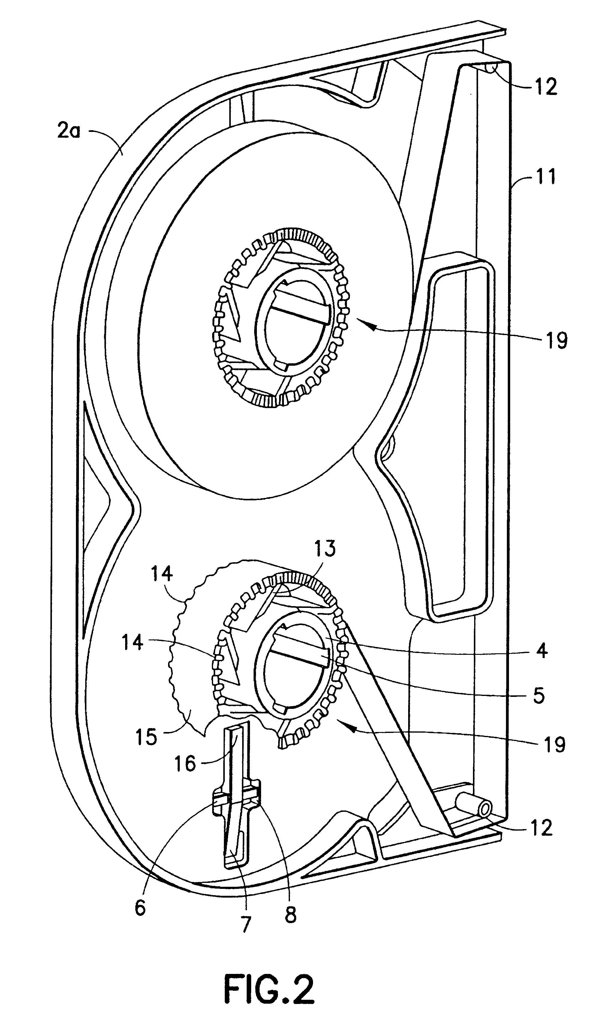
The cassette 1 shown comprises a housing 2, which is preferably assembled from two identical half-housing parts 2a, 2b, the half-housings being detachable one from the other along a dividing joint 3. On the housing 2, on the upper and lower sides, there are guide faces 18, on which the cassette 1 can be guided in a ribbon station and by means of which cassette vertical positioning within the ribbon station defined and fixed. The positioning of the cassette 1 in the horizontal direction within the insertion shaft of the ribbon station is carried out by means of a positioning opening 10 in side walls of the cassette 1. When the insertion shaft is closed...


PUM

PropertyMeasurementUnit
winding forceaaaaaaaaaa
forceaaaaaaaaaa
thermoplasticaaaaaaaaaa

Abstract

Cassette for thermal transfer ribbon for setting images on printing plates, having spools to hold the thermal transfer ribbon inside a housing, the spools having some play with respect to the housing of the cassette, and the spools being capable of being positioned with respect to the housing such that neither the spools nor the thermal transfer ribbon touch the housing during spooling operations.

Description

1. Field of the InventionThe invention relates to a cassette for thermal transfer ribbon for setting images on printing plates, the cassette having spoons inside a housing for holding the thermal transfer ribbon.2. Description of the Related ArtEP 0 698 488 B1 discloses a strip-like transfer foil for setting images on printing plates by means of a laser beam. The strip width of the transfer foil is small, as referred to the printing-plate width, and the transfer foil is spooled from a supply roll on to a rewind roll by means of a ribbon transport device and, in the process, led between printing plate and laser head. In order to reach the complete image area of the printing plate, the plate cylinder is rotated under control and the ribbon transport device, together with the laser head, is moved under control over the width of the plate cylinder on a transversing unit.In order to carry out a thermal transfer process, the individual rolls of ribbon have to be inserted manually into the...

Claims


Application Information

Patent Timeline
Patent Type & Authority Patents(United States)
IPC IPC(8): B41J32/00B41M5/26B41C1/055B41J31/00B41M5/382
CPCB41J32/00B41M5/26B41M5/38221
Inventor HARTMANN, THOMAS
Owner MANROLANAD AG
Features
  • R&D
  • Intellectual Property
  • Life Sciences
  • Materials
  • Tech Scout
  • Unparalleled Data Quality
  • Higher Quality Content
  • 60% Fewer Hallucinations
Learn More