Inkjet recording device capable of controlling ejection timing of each nozzle individually
a recording device and nozzle technology, applied in the direction of power drive mechanism, printing, inking apparatus, etc., can solve the problems of increasing the manufacturing cost of the device, difficult to change the analog voltage in such a manner, and inapplicability of multi-nozzle driving circuits
- Summary
- Abstract
- Description
- Claims
- Application Information
AI Technical Summary
Benefits of technology
Problems solved by technology
Method used
Image


Examples
first embodiment
FIG. 2 shows an inkjet recording device 1 according to a As shown in FIG. 2, the inkjet recording device 1 includes a sheet feed mechanism 601, a recording head 501, and a rotary stage 154. The recording head 501 is mounted on the sheet feed mechanism 601, and the rotary stage 154 is attached to the recording head 501.
As shown in FIG. 3, the sheet feed mechanism 601 includes a continuous recording sheet 602, a guide 603, a driving roller 604, a rotary encoder 605, and a transport mechanism (not shown). The transport mechanism transports the continuous recording sheet 602 along the guide 603 in a sheet feed direction Y so that the continuous recording sheet 602 reaches beneath the recording head 501 and discharged via the driving roller 604. The rotary encoder 605 is attached to the driving roller 604, and generates a sheet-position indication pulse 108 in accordance with a location of the continuous recording sheet 602 with respect to the sheet feed direction Y in a precise manner....
second embodiment
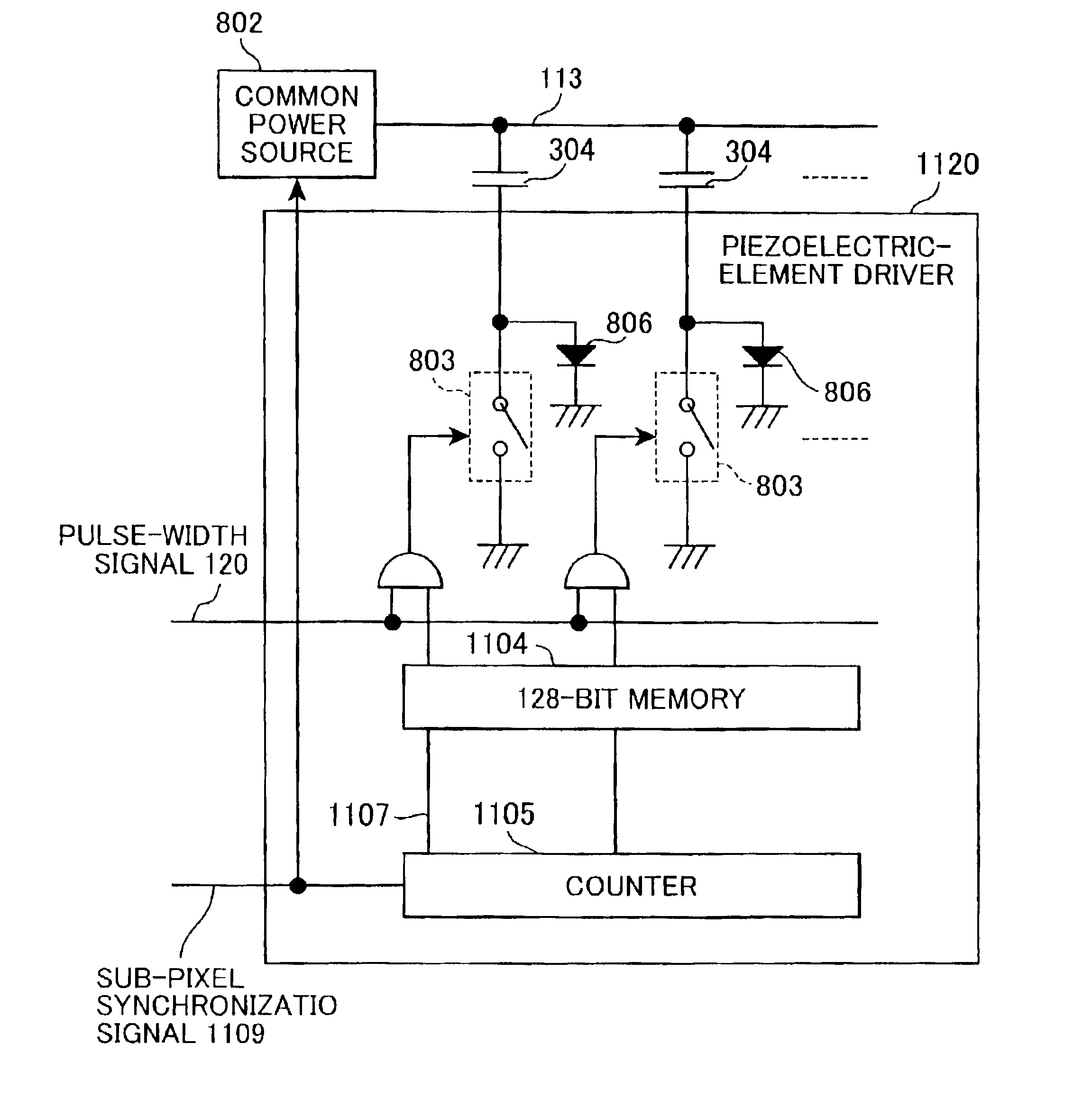
Next, the present invention will be described while referring to a Table 3, a Table 4, and FIGS. 11 and 12.
TABLE 4
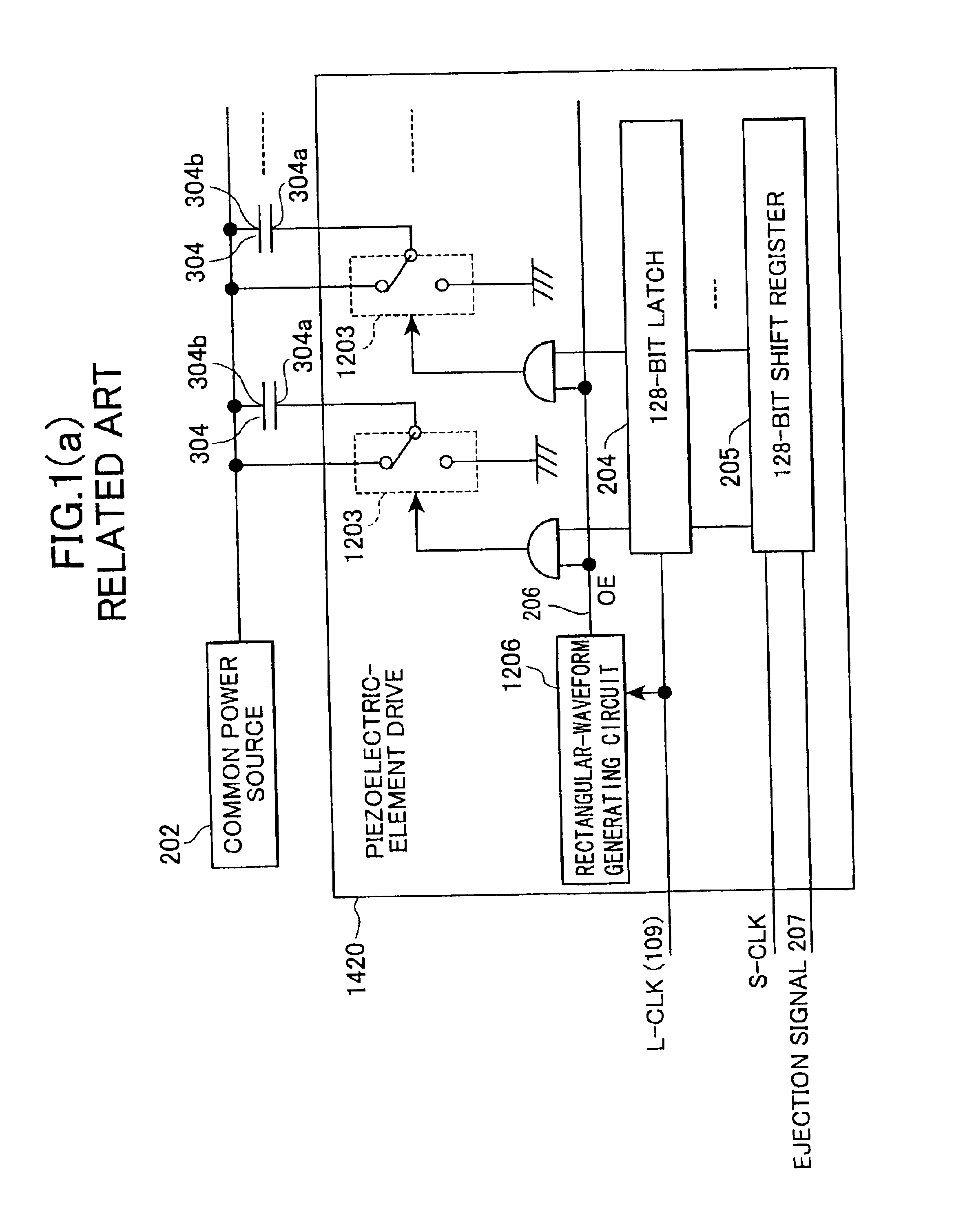
The mass of an actually ejected ink droplet differs by 10% to 20% among the nozzles 300. In order to overcome this problem, there have conventionally been provided analog-driving-signal generation devices each for corresponding one of the nozzles 300, so that each nozzle 300 is applied with an analog driving signal 406 specifically prepared for the nozzle 300 to have appropriate voltage, pulse width, and the like. This method is called all-amount trimming. However, it is not practical to provide so many number of analog-driving-signal generation devices for large number of nozzles 300. In order to overcome these problems, the present invention provides a high-speed ejection device capable of all-amount trimming without needing a large number of analog-driving-signal devices for all nozzles 300. Description of the ejection device according to the present embodiment will b...
third embodiment
Next, the present invention will be described. Here, the components similar to that of the above-described embodiments will be assigned with the same numberings, and their explanation will be omitted.
An inkjet recording device 2 according to the present embodiment shown in FIG. 13 has a similar configuration as that of the inkjet recording device 1 of the first embodiment. However, the inkjet recording device 2 includes a pulse-width changing unit 121 and a recording head 510 instead of the digital-ejection-signal generation unit 111 and the recording head 501. The recording head 510 includes a plurality of nozzle modules 401 and a plurality of piezoelectric-element drivers 112. Although not shown in the drawings, the pulse-width changing unit 121 includes a plurality of pulse-width changing members each for corresponding one of the nozzle modules 401.
As shown in FIG. 14, each nozzle module 401 is formed with 128-number of nozzles 300 aligned with equidistance from each other. Becau...
PUM
 Abstract
Description
Claims
Application Information
 - R&D
- Intellectual Property
- Life Sciences
- Materials
- Tech Scout
- Unparalleled Data Quality
- Higher Quality Content
- 60% Fewer Hallucinations
Browse by: Latest US Patents, China's latest patents, Technical Efficacy Thesaurus, Application Domain, Technology Topic, Popular Technical Reports.
© 2025 PatSnap. All rights reserved.Legal|Privacy policy|Modern Slavery Act Transparency Statement|Sitemap|About US| Contact US: help@patsnap.com