Check patentability & draft patents in minutes with Patsnap Eureka AI!

Method and apparatus for a rebound system and adjustable resistance system

a technology of resistance adjustment and rebound system, which is applied in the field of method and apparatus, can solve the problems of inability to manufacture, difficult to execute awkward movements, and new problems for individuals changing the resistance exerted on the carriage, and achieve the effect of convenient maintenance and replacement of damaged elastic members and convenient manufactur

Inactive Publication Date: 2004-12-07
GRAHAM GARY
View PDF3 Cites 9 Cited by
  • Summary
  • Abstract
  • Description
  • Claims
  • Application Information

AI Technical Summary

Benefits of technology

The solution enables easier and more convenient resistance adjustment, reduces the mass of non-operative elastic members, prevents damage to elastic members, and simplifies maintenance, while providing an exponentially increasing force for enhanced exercise performance.

Problems solved by technology

This presents a new problem for the individual changing the resistance exerted upon the carriage.
This was an awkward movement that was difficult to execute and other times was not feasible because of the immediate location of the wall.
Another issue with the earlier designs was that the elastic members that were not in an operative position traveled with the carriage.
A further issue with the earlier designs was that the elastic members would develop cracks on the interior surfaces near the head or handle portions.
After many cycles of changing elastic members from an inoperative positioned to an operative position, the elastic members would break as a result from a crack that began on the interior surface near the end portion of the barbed insert of the head member.
However, the prior art rebound systems were difficult to adjust in the longitudinal range of motion of travel of the carriage, and further, they were more expensive to produce.

Method used


Image

  • Method and apparatus for a rebound system and adjustable resistance system
  • Method and apparatus for a rebound system and adjustable resistance system
  • Method and apparatus for a rebound system and adjustable resistance system

Examples


first embodiment

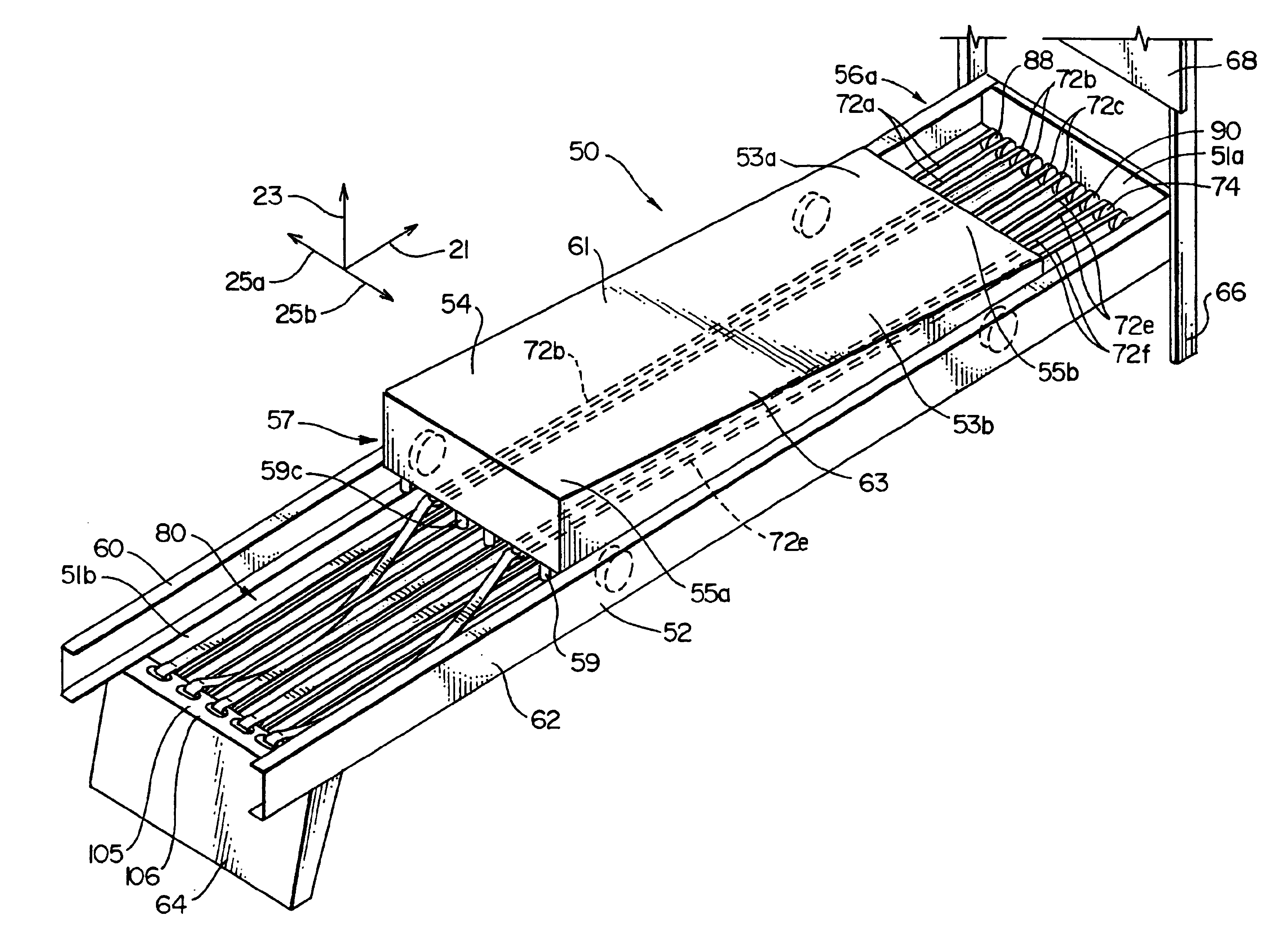
In the first embodiment as seen in FIG. 3, the carriage 54 has a head portion 55a, a foot end portion 55b, a leftward lateral portion 61 and a rightward lateral portion 63. The leftward lateral portion 61 is defined as any point left of the longitudinal center axis of the carriage 54. Likewise, the rightward lateral portion 63 is defined as any point right of the longitudinal center axis of the carriage 54.

As seen in FIGS. 3, 4 and 5 the first embodiment has an engagement section 57 that is located in the head portion 55a of the carriage 54 and comprises a plurality of downwardly extending fingers 59.

The resistance system 56 comprises a plurality of elastic members or loops 72, a first pulley system 74, a mounting portion 76, a support system 78 and a mounting strap system 80.

In general, the elastic members 72 are rigidly mounted to the mounting portion 76 and extend around the first pulley system or base portion 74 back to the head portion of the frame 52 to the support system 78. ...

second embodiment

the present invention is shown in FIG. 12. This embodiment is substantially similar to the first embodiment with slight modifications. The apparatus 200 comprises a support structure or frame 202, a carriage 204, a resistance system 206, and a rebound or range of motion control system 208. As seen in FIGS. 12-14, the frame 202 comprises a first support 208 and a second support 210 that are located at the head end and foot end longitudinal locations. The first support 208 has an upper portion 209. On the headward face of the first support 208 there are located a plurality of support pegs 211 that will be further discussed herein. The frame further comprises two longitudinally extending members 212 and 214 that are angled upwardly when traveling from the foot end to head end in the longitudinal direction.

The carriage 204 is substantially similar to the carriage 54 of the first embodiment with the exception the engagement section 215 as seen in FIG. 12 comprises a plate 217 that forms ...

third embodiment

FIG. 17 shows a third embodiment where there is the apparatus 300 that comprises a frame 302, a carriage 304, and a resistance system 306.

The resistance system 306 comprises a plurality of elastic members 308, an engagement system 310 and a pulley system 312. The elastic members 308 are similar to the elastic members in the first embodiment and can be made from bungee cord material. The resistance system 306 travels with the carriage unlike the resistance system 56 of the first embodiment. The elastic members 308 have a first location 313, a base portion 314 and a head portion 316. Located at the head portion 316 is a tab member 318. To place a elastic member 308 to an operative position the therapist or exercising participant grabs the tab member 318 and pulls it to the lower position onto the fingers 320 that are mounted to the frame 302.

FIG. 19 shows a fourth embodiment that is similar to the second embodiment. The main difference in this embodiment is that the mounting strap sys...


PUM


Abstract

The exercise apparatus comprises a frame and a carriage. A resistance system resists movement of the carriage with respect to the frame and the longitudinally headward direction. The resistance system allows the resistance to be changed at the head end portion of the frame and further does not require elastic members to travel with the carriage when they are not use. The rebound system that adjusts the range of motion of the carriage comprises two flexible members attached to the carriage and the frame and a resistance member is attached to a central portion of the flexible members and resists lateral seperation of the central portions of the flexible members.

Description

The invention relates to an exercise and therapeutic apparatus and more specifically a rebound system and an improved method of altering the resistance of the carriage that the exercise participant travels upon.The invention relates to the art of exercise apparatuses that generally consists of a stationary frame, a moving carriage, a kickplate, a resistance system and a rebound system. The exercising orientated is positioned in a supine position on the carriage as it travels in a longitudinally oscillating or reciprocating motion by exerting a force upon a kickplate that is attached to the foot end portion of the frame or by pulling upon arm cords connected head end portion of the frame.Prior exercise apparatuses that have been disclosed in U.S. Pat. Nos. 5,042,797 and 5,364,327 that are also applications made by the inventor, disclose resistance systems that allow adjustability from the foot end portion (the portion where the kickplate is located) of the exercise apparatus only. Th...

Claims


Application Information

Patent Timeline
Patent Type & Authority Patents(United States)
IPC IPC(8): A63B21/02A63B22/00A63B21/055A63B23/04
CPCA63B21/0552A63B22/0087A63B21/154A63B22/00A63B21/00069A63B21/0428A63B21/0557
Inventor GRAHAM, GARY
Owner GRAHAM GARY
Features
  • R&D
  • Intellectual Property
  • Life Sciences
  • Materials
  • Tech Scout
  • Unparalleled Data Quality
  • Higher Quality Content
  • 60% Fewer Hallucinations
Learn More