Supercharge Your Innovation With Domain-Expert AI Agents!

Flexible conveyor

a conveyor and flexible technology, applied in the direction of conveyors, conveyor parts, transportation and packaging, etc., can solve the problems of unfavorable transportation of passengers, so as to avoid unfavorable transportation and avoid unfavorable transportation. , the effect of reducing the amount of slack

Active Publication Date: 2005-02-22
AMMERAAL BELTECH MODULAR
View PDF12 Cites 6 Cited by
  • Summary
  • Abstract
  • Description
  • Claims
  • Application Information

AI Technical Summary

Benefits of technology

In a further advantageous embodiment one or more of the conveyor belt support means projecting from its underside comprise roller means or ball means for slidingly supporting at least part of the conveyor. This embodiment is especially advantageous for use in loading bays of air planes, trucks, and the like where it can be advantageous to have the conveyor slidingly placed on the floor of the cargo bay. The rollers or balls make for very easy handling of the conveyor as it can be pushed / dragged manually into the most advantageous position in relation to the items, for example luggage, which need to be transferred onto the conveyor. Because of the flexibility built into the conveyor by means of the carrying chain, it is possible to side-flex the conveyor belt around fixed obstacles placed in the cargo bay so that even the furthest regions of the loading bay area can be reached with the conveyor according to the invention.
In a further advantageous embodiment, sides connecting the edges of the conveyor belt support means with the conveyor belt guidance means of each chain link are provided. These sides make it possible in this further advantageous embodiment to increase the load on the upper side of the conveyor as part of the load is being transferred directly through the sides down to the guidance means which then can transfer the load, either to the chain link itself, or to support means attached to that particular chain link.
The means for guiding the conveyor belt around the turn mainly serves two purposes. Firstly, it ensures that no buckling will occur in the conveyor belt when it goes through the turn at the end of the conveyor, and secondly it alleviates some of the slack arising during use of the belt.
By using for example side-flexing belts such as Uniflex SNB side-flexing provided by uni-chains A / S, Denmark, the distance between two belt links in the conveyor belt when being pulled on the upper side will be longer than the distance between two chain links on the under side when they are pushed back to the beginning of the belt. The difference in length can be up to 40%. In addition to this, an additional 10% difference can occur due to wear in the belt construction. The guidance means provided on the inside of the sides helps to forcibly push the conveyor belt chain links together so that no buckling occurs in the conveyor due to the flexible length of the conveyor belt.
In a still further advantageous embodiment of the invention, the conveyor belt is driven by a pinion drive engaging the belt adjacent to at least one of the means arranged at each end of the conveyor. By having a simple engagement with the openings in the conveyor belt a very direct transmission is provided. When these means are furthermore cooperating with the guidance means for guiding the conveyor belt through the turn, undesired buckling of the belt can be avoided, even under high loads.

Problems solved by technology

The total conveyor system from the first station to the secondary stations thereby becomes complex and expensive.
The height in a typical civil commuter plane is between 90 and 150 cm which puts a strain on the back of the person lifting the suitcases from the loading bay and onto the conveyor.
Furthermore, the traditional type of conveyor used for unloading air planes can only reach a limited distance into the loading bay.
This requires a further cumbersome routine and requires the continual redoing of the conveying structure as the luggage is unloaded from one end whereby the distance to convey increasingly becomes longer.

Method used


Image

  • Flexible conveyor
  • Flexible conveyor
  • Flexible conveyor

Examples


Embodiment Construction

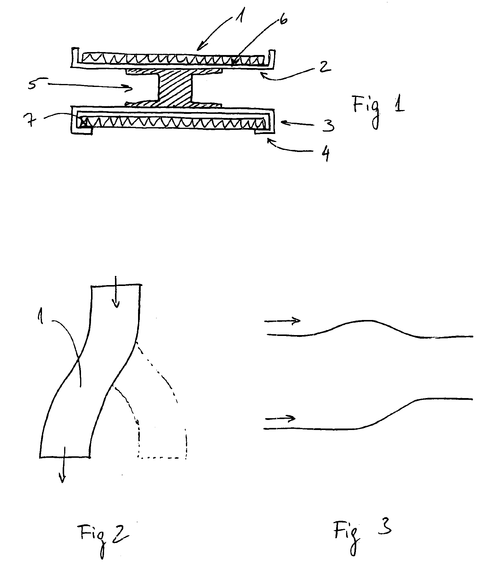
FIG. 1 schematically illustrates a cross-section through an inventive conveyor according to the invention. On the upper side of the structure the conveyor belt 1 is supported by conveyor belt support means 2. On the underside of the conveyor, conveyor belt guidance means 3 are provided. These guidance means 3 comprise a flange 4 which supports the conveyor belt when it is travelling back to the beginning of the conveyor. The load-carrying structure 5 comprises a load-carrying chain consisting of a number of interconnected chain links. The chain links in the load-carrying structure are interconnected in such a way that they can articulate in all three dimensions.

As is evident from the schematic presentation in FIG. 1, the conveyor belt support means as well as the conveyor belt guidance means are exposed to wear. When the conveyor belt for example is of the type SNB Flexible Belts® provided by uni-chains A / S, Denmark, the belt is advantageously made from a mouldable plastic material....


PUM


Abstract

The present invention relates to a flexible conveyor comprising a carrying structure and a conveyor belt where the upper side is defined by the loading surface of the conveyor belt.The invention provides a flexible conveyor comprising a carrying structure and a conveyor belt where the upper side is defined by the conveyor belt loading surface characterised in that the carrying structure comprises a load-carrying chain where each link in the chain on its upper side comprises conveyor belt support means, and on its underside conveyor belt guidance means, and that each load-carrying chain link is articulately joined for movement in three dimensions relative to the adjacent links and further that the conveyor belts loading surface is supported by the conveyor belt support means, and further that means are provided in each end of the flexible conveyor about which the conveyor belt is guidably turned.

Description

This application claims the benefit of Danish Application No. 2002 01510 filed Oct. 8, 2002.BACKGROUND OF THE INVENTIONThe present invention relates to a flexible conveyor comprising a carrying structure and a conveyor belt where the upper side is defined by the loading surface of the conveyor belt.A typical conveyor comprises a carrying structure which is a structure around which the belt is arranged. The carrying structure is usually made up of a stiff construction, for example made from steel, defining the path along which the conveyor belt will have to travel. In order to be able to convey goods on the conveyor belt, the carrying structure comprises a support structure for the belt so that the belt will be able to travel in a substantially horizontal or slightly inclined forward direction.The conveyor belt can be in the shape of any suitable belt construction. If it is desirable to have a conveyor which conveys goods in a straight line, but at different levels, conveyor belts ma...

Claims


Application Information

Patent Timeline
IPC IPC(8): B65G21/00B65G15/60B65G21/14B65G15/62B65G15/16
CPCB65G21/14B65G15/16
Inventor DAMKJ.AE BUTTED.R, POUL ERIK
Owner AMMERAAL BELTECH MODULAR
Features
  • R&D
  • Intellectual Property
  • Life Sciences
  • Materials
  • Tech Scout
  • Unparalleled Data Quality
  • Higher Quality Content
  • 60% Fewer Hallucinations
Learn More