Check patentability & draft patents in minutes with Patsnap Eureka AI!

Stand-off for fixing thermal protection panels

a technology of thermal protection panels and stand-offs, which is applied in the field of thermal protection, can solve the problems of difficult to provide such a mechanical connection in satisfactory manner, unable to meet the requirements of mechanical connection,

Inactive Publication Date: 2005-05-03
SAFRAN CERAMICS SA
View PDF19 Cites 14 Cited by
  • Summary
  • Abstract
  • Description
  • Claims
  • Application Information

AI Technical Summary

Benefits of technology

[0012]The invention seeks to remedy the above-specified drawbacks and to provide a system for fixing thermal protection panels that enables the panels to move relative to the wall of the structure to be protected in a plurality of directions without degrading the reliability with which the panel is attached, particularly against applied mechanical loads, while nevertheless providing for elastic return after loading.
[0014]The stand-off obtained in this way allows the panel to move relative to the structure to be protected, and vice versa, in two distinct directions, while nevertheless conserving good stiffness against crushing and tear-off forces applied to the panel.

Problems solved by technology

Consequently, it appears difficult to provide such a mechanical connection in satisfactory manner, particularly since even when there is only one thermal load it is still necessary to be able to position the fixing systems very accurately relative to the deformation they are to absorb.
If connections which deform in one direction only are not positioned accurately in orientation, then transverse forces can be generated leading to the fastening or to the structure breaking.
However, problems due to transverse forces remain.
In order to avoid transverse forces, the connecting rods could be mounted via ball-and-socket joints at both ends, however when the panels expand, displacement thereof in a direction parallel to the outside aerodynamic shape would give rise to displacement in the normal direction, in turn giving rise to excessive modification to the aerodynamic shape defined by the panels.
The problem of elastic return would also remain.
Unfortunately, it is known that materials are much rougher in space than in the atmosphere.
In addition, thermal loading takes place at the same time as compression loading on the panels which makes sliding between the elements even more difficult.

Method used


Image

  • Stand-off for fixing thermal protection panels
  • Stand-off for fixing thermal protection panels
  • Stand-off for fixing thermal protection panels

Examples


Embodiment Construction

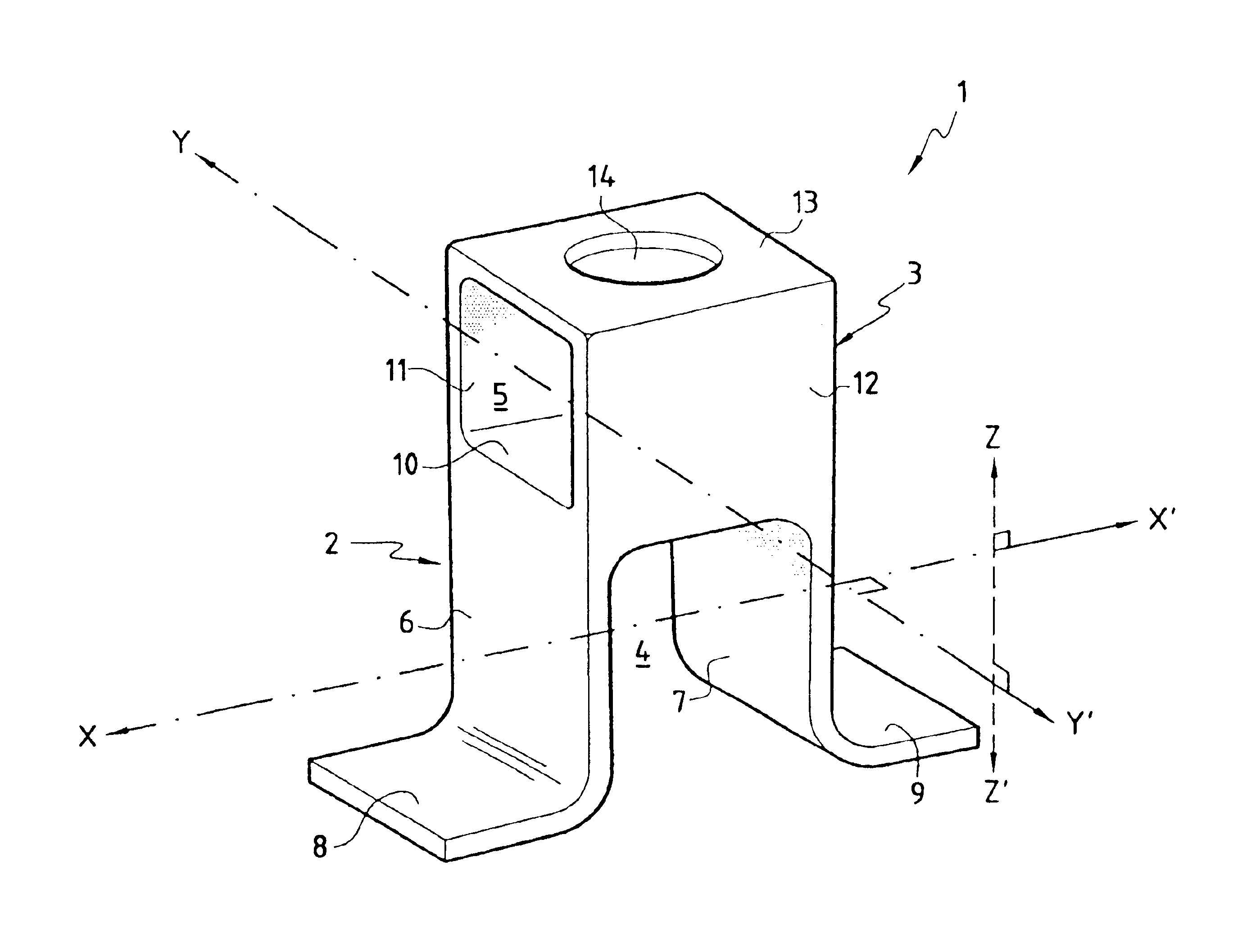
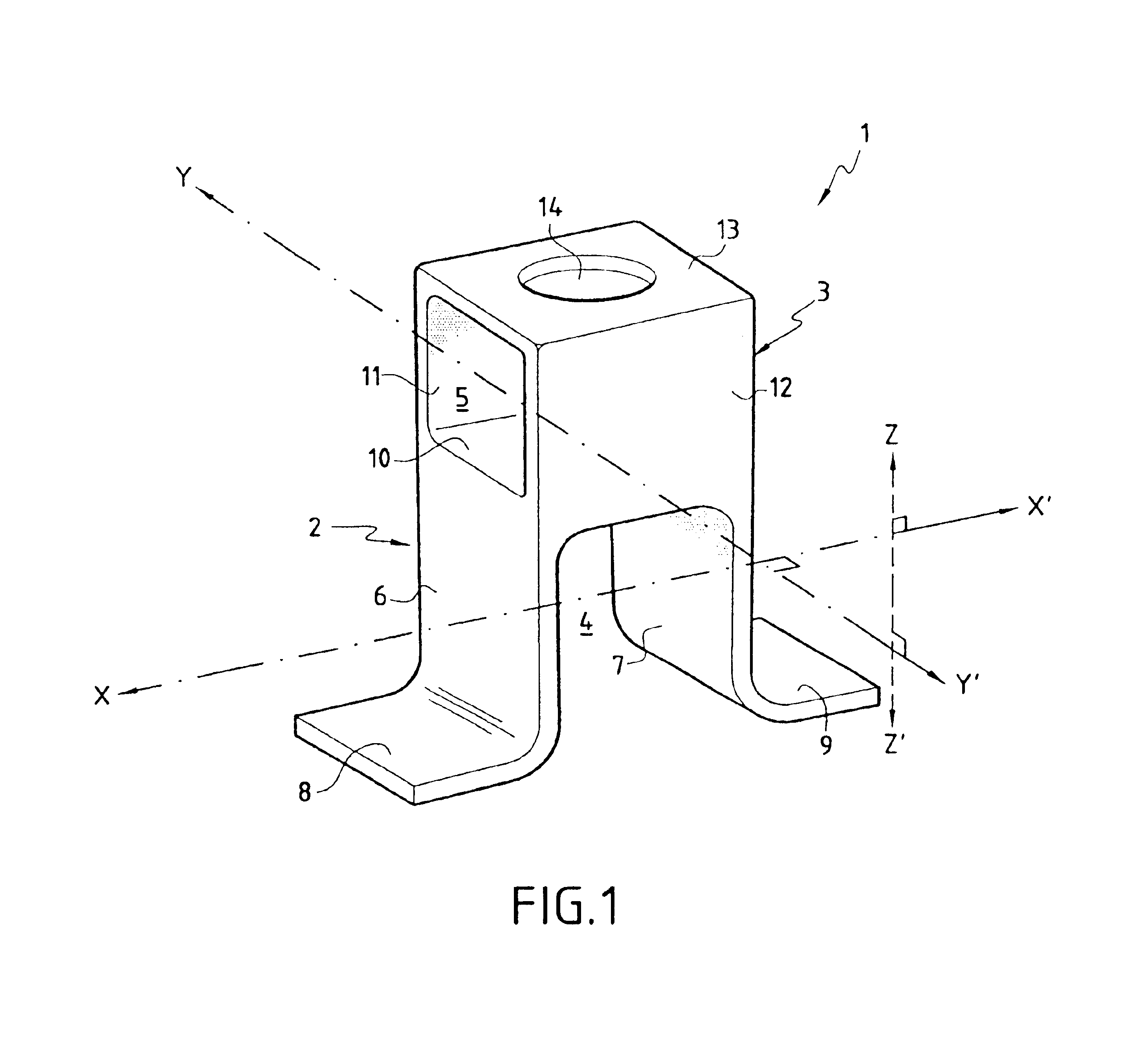
[0026]The above-described invention relates mainly to a stand-off in a thermal protection structure. In the present description, the term “stand-off” designates an element for fixing a mechanical thermal protection panel on the structure of a vehicle such as a vehicle for reentering the atmosphere. More precisely, it is an intermediate element that provides a rigid mechanical connection between the panel and the structure of the vehicle, serving to lengthen the thermal conduction path so as to isolate the structure, and accommodating differential deformation of the panel relative to the structure during thermomechanical loading.

[0027]The thermal protection function under consideration herein is to protect a structure such as a vehicle for reentering the atmosphere or a cryogenic tank against high temperature heat fluxes that are encountered in its operating environment. For this purpose, the thermal protection device comprises a panel which receives the high temperature heat flux on...


PUM


Abstract

In order to accommodate differential expansion between thermal protection panels and a structure to be protected, the present invention provides a stand-off for holding the panels, the stand-off comprising a first portion allowing displacements to take place in a first direction and a second portion allowing displacements to take place in a second direction. Each of the two portions also presents a high degree of stiffness in a direction corresponding to tear-off and crushing forces applies to the panels. The stand-off is made as a single piece having first and second recesses formed therein in order to make the first and second portions respectively in determined orientations so that the resulting stand-off allows displacements to take place in two distinct directions perpendicular to the tear-off and crushing directions.

Description

FIELD OF THE INVENTION[0001]The present invention relates to the field of thermal protection, and more particularly to fixing panels in this type of protection.PRIOR ART[0002]Thermal protection devices of the kind present on vehicles for reentering the atmosphere, for example, are generally made up of panels which act not only to provide the outside wall of the vehicle with mechanical strength, but also to provide it with thermal insulation.[0003]Nevertheless, recent projects have shown that it can be advantageous to separate the outside wall function from the thermal insulation function. Under such circumstances, the thermal protection device can comprise a panel of thermostructural composite material constituting the outside wall of the device, together with internal insulation placed between the inside face of the panel and the wall of the structure to be protected. Under such circumstances, the panels need to be fixed at a distance from the wall of the structure that is to be pr...

Claims


Application Information

Patent Timeline
Patent Type & Authority Patents(United States)
IPC IPC(8): B64G1/58B64G1/22F16B19/00F16B19/02F16B5/02F16C11/12F16C11/04F16M11/12F16M11/02
CPCB64G1/58F16B5/0241F16B19/02F16M11/043F16M11/12F16M13/02F16C11/12Y10S248/913F16C2326/47
Inventor SOYRIS, PHILIPPE
Owner SAFRAN CERAMICS SA
Features
  • R&D
  • Intellectual Property
  • Life Sciences
  • Materials
  • Tech Scout
  • Unparalleled Data Quality
  • Higher Quality Content
  • 60% Fewer Hallucinations
Learn More