Sub-sea blow case compressor

Inactive Publication Date: 2005-06-21
CONOCOPHILLIPS CO
View PDF23 Cites 46 Cited by
  • Summary
  • Abstract
  • Description
  • Claims
  • Application Information

AI Technical Summary

Benefits of technology

[0007]In one embodiment the present invention relates to the submersible compressing apparatus which is attached to a gas/liquid separator. The gas/liquid separator has an opening for connection to the well head, a gas exit opening and a production liquid exit. A separator gas conduit is connected to the gas exit opening of the gas/liquid separator and is connected to a gas valve. Connected to the liquid/gas separator is a first compressor tank which has first and second openings. The first opening of the compressor tank is connected to the gas valve by a production conduit and the production conduit also has a gas production valve connected to it. The gas production valve is connected to a conduit for carrying the gas to a desired location, such as to the surface or to the shore. Connected to the second opening of the compressor tank is a liquid conduit. The liquid conduit is connected to a inlet valve and a tank valve. The tank valve is connected to a evacuation conduit which is connected to a pump. In operation, raw material from the well is separated into liquid and gas phases in the liquid/gas separator. The inlet valve to the compressor tank is opened and water from the environment is allowed to flood the tank. The inlet valve is then closed and the tank valve opened. The pump is started and water is pumped from the compressor tank. As a result the pressure in the compressor tank is decreased and the gas valve is opened allowing gas to flow from the liquid/gas separator into the compressor tank. Once the desired amount of gas has flowed into the compressor tank the tank valve is closed and the pump stopped. Thereafter, the gas valve to the liquid/gas separator is closed and the gas production valve is opened. Then the inlet valve to the compressor tank is opened allowing water to again fill the tank. The hydrostatic head of the water surrounding the compressing apparatus in the environment provides pressure to compress and push the gas out of the first compressor tank. When a desired amount of water has enter

Problems solved by technology

The disadvantages of mechanical gas compressors include that they often require more power than is practical t

Method used


Image

  • Sub-sea blow case compressor
  • Sub-sea blow case compressor
  • Sub-sea blow case compressor

Examples


Embodiment Construction

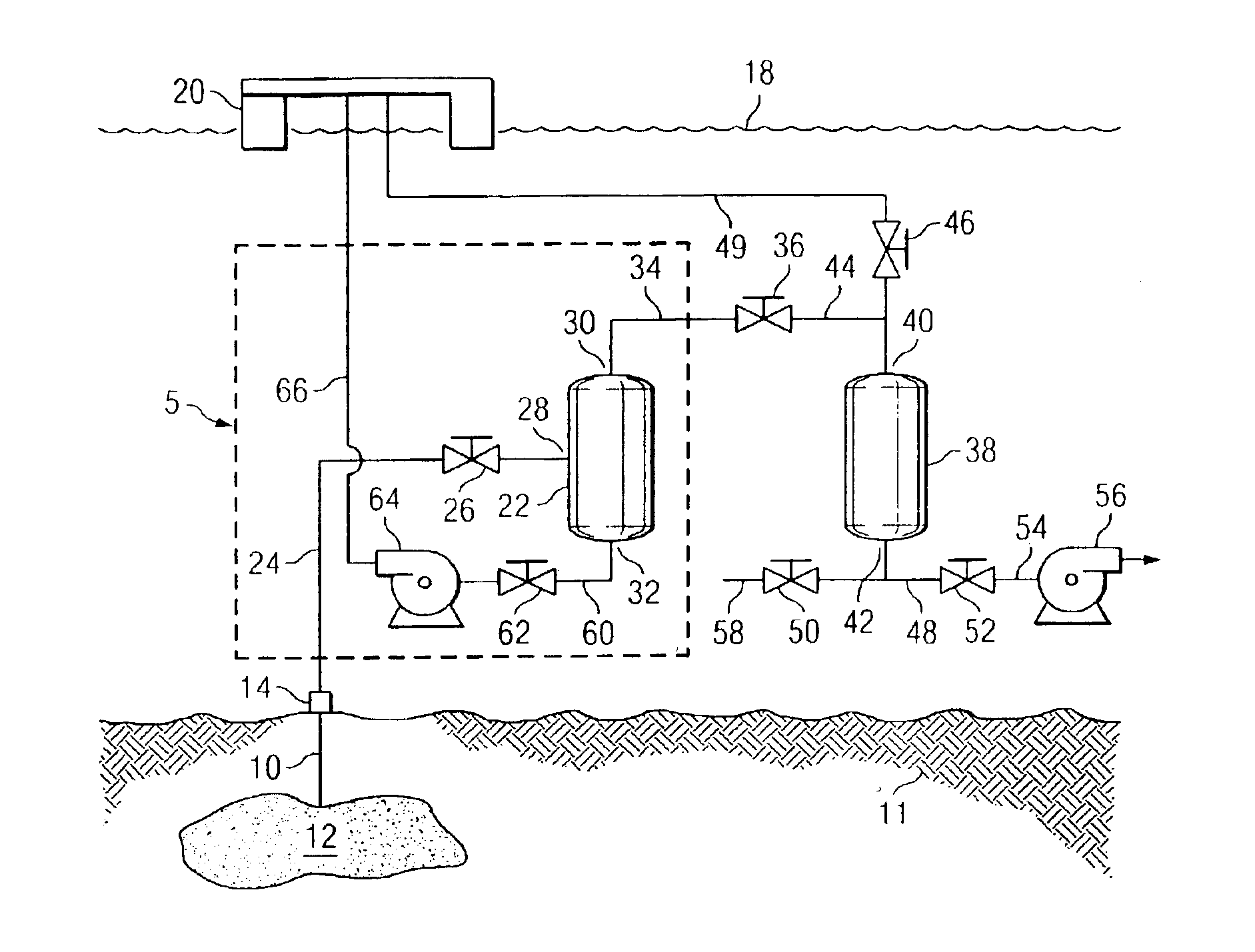
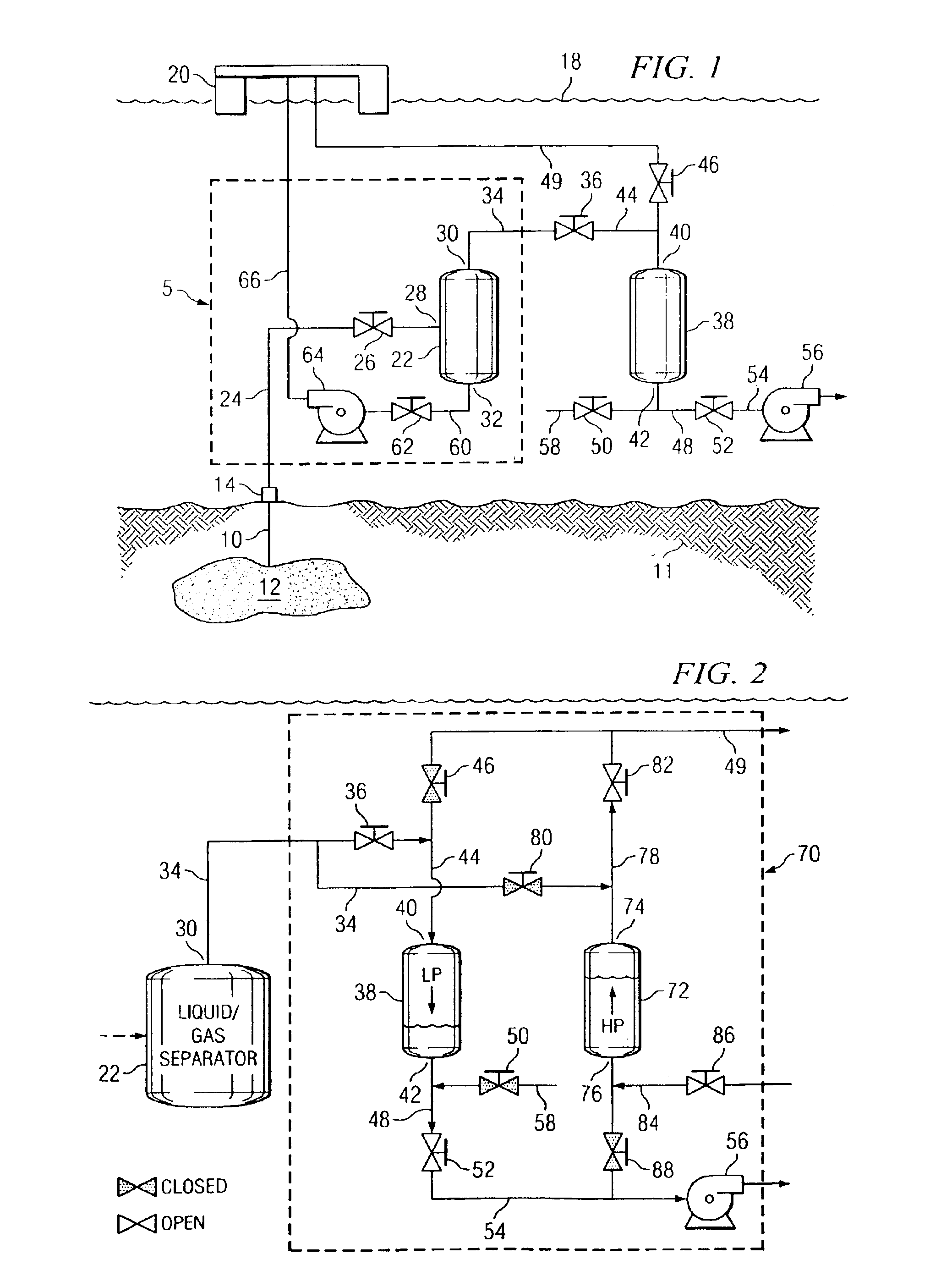
[0020]FIG. 1 illustrates one embodiment of a submersible compressing apparatus of the present invention. It is believed that the invention will have the greatest application to offshore production, and thus, the preferred embodiments will be discussed in relation to that environment. It being understood that the invention can also be employed in other water environments. A well bore 10 has been drilled through the seabed 11 into an offshore petroleum reservoir 12 and has a well head 14 on the sea bed 16. At the surface 18 of the sea is platform 20. The well head 14 is connected to a liquid / gas separation system 5, enclosed by the dashed box. The primary component of the liquid / gas separation system 5 is the liquid / gas separator 22. The liquid / gas separator 22 is connected to the well head 14 by well head conduit 24. Interposed in well head conduit 24 is well head valve 26 which controls flow of the raw material produced by the well into liquid / gas separator 22. Liquid / gas separator ...


PUM


Abstract

A sub-sea submersible compressing apparatus having at least one compressor tank. A compressor tank is configured to receive gas from a gas/liquid separator and has an inlet for water. The compressor further comprises a pump to pump water from the compressor tank thereby drawing gas into the compressor tank from the gas/liquid separator. Valves are provided to shut off gas flow from the liquid/gas separator and to permit gas flow from the compressor tank to a predetermined location such as a recovery line for transferring the gas to the surface or other location. The gas contained within the compressor tank is compressed by allowing water to flow back into the compressor tank, thereby compressing the gas and forcing it from the compressor vessel. Two or more compressor tanks can be provided to facilitate a continuous operation by timing of the water flow to and from each of the compressor tanks.

Description

TECHNICAL FIELD[0001]The present invention relates to compressor apparatus for gas production from underwater wells. In particular the invention relates to a compressor for gas production from an underwater well.BACKGROUND OF THE INVENTION[0002]The invention relates to a submersible compressing station for a well producing gas and oil. The invention has the greatest applicability to offshore oil and gas production, although it may be employed in lakes and bays as well. In such production, wells are drilled from a platform or a semi-submersible vessel, or a drill ship, etc. on the surface of the water into the subsea formations. The well bore is drilled into a petroleum producing formation and the well is completed, i.e. put in condition for producing gas and oil. Many times oil present in a hydrocarbon reservoir contains dissolved gas and the capability of the oil to hold such gas decreases as the pressure decreases and temperature increases.[0003]Once a well is placed in production...

Claims


Application Information

Patent Timeline
IPC IPC(8): E21B43/00E21B43/34E21B43/36E21B43/01F04F1/00F04F1/06
CPCE21B43/01F04F1/06E21B43/36
Inventor CHOI, MICHAEL S.ELLIOT, DONALD C.
Owner CONOCOPHILLIPS CO
Why Eureka
Try Eureka