Check patentability & draft patents in minutes with Patsnap Eureka AI!

Fixation clamp device for hose fittings

a technology for fixing clamps and fittings, which is applied in the direction of hose connections, pipe joints, pipe elements, etc., can solve the problems that typical fixation clamp devices and may not be used to solidly couple pipes or conduits

Inactive Publication Date: 2005-06-21
CHU HENRY C +1
View PDF19 Cites 12 Cited by
  • Summary
  • Abstract
  • Description
  • Claims
  • Application Information

AI Technical Summary

Benefits of technology

The device provides a secure and adjustable mechanism for coupling hoses and fittings, preventing them from dislodging during high-pressure fluid flow, making it suitable for flushing and leakage testing applications.

Problems solved by technology

However, the typical fixation clamp devices may not be used to solidly couple pipes or conduits having pressurized air or fluid flown therethrough.
However, the typical fixation clamp devices also may not be used to solidly couple pipes or conduits having pressurized air or fluid flown therethrough.
However, the typical fixation clamp devices also may not be used to solidly and adjustably couple pipes or conduits together.

Method used


Image

  • Fixation clamp device for hose fittings
  • Fixation clamp device for hose fittings
  • Fixation clamp device for hose fittings

Examples


Embodiment Construction

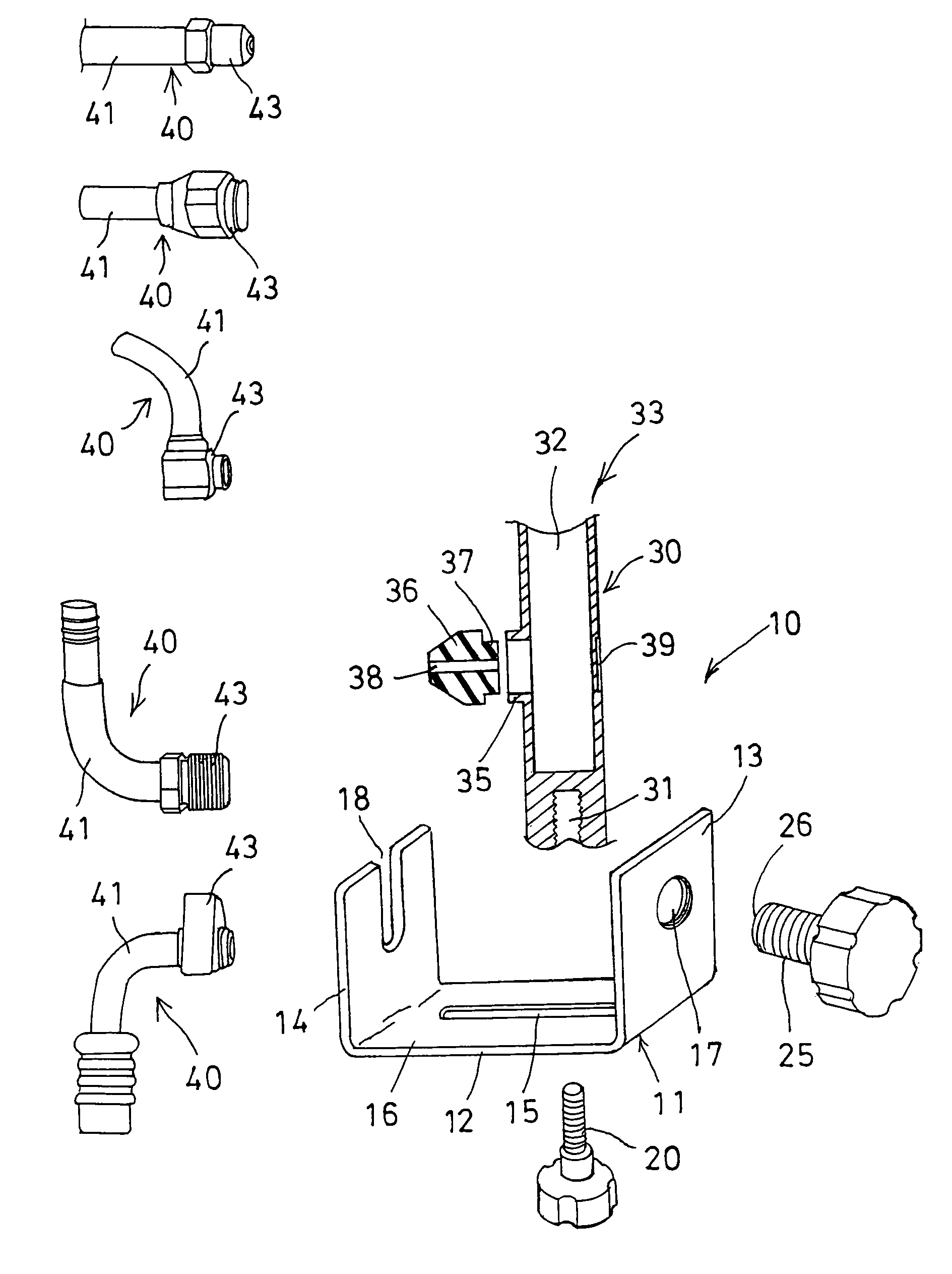
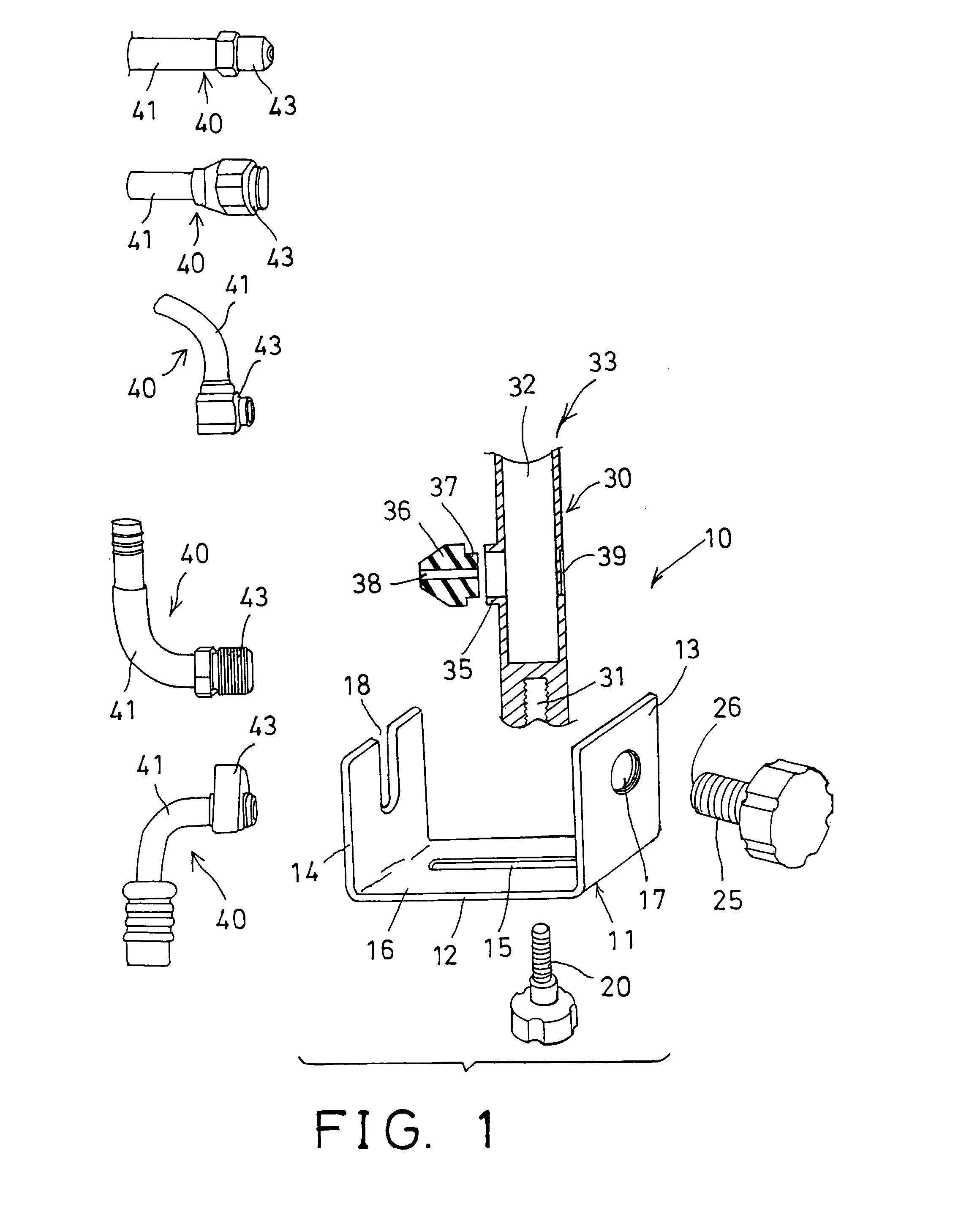
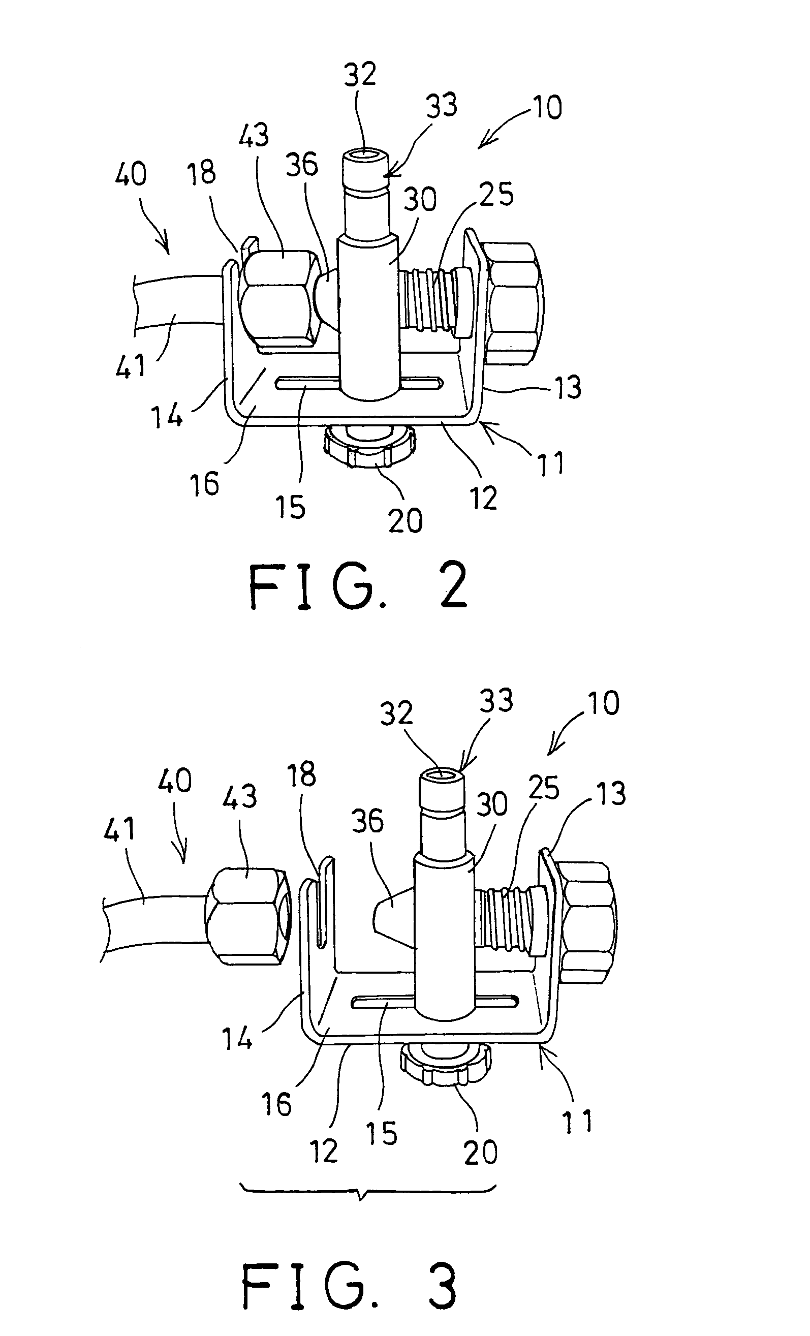
[0024]Referring to the drawings, and initially to FIGS. 1–3, a fixation clamp device in accordance with the present invention is generally indicated with a reference numeral “10” and comprises a U-shaped bracket 11 including a base plate 12, and two flaps 13, 14 extended from two ends of the base plate 12, and preferably perpendicular to the base plate 12, to form or define a space 16 in the bracket 11 and between the flaps 13, 14. The base plate 12 includes a longitudinal channel 15 formed therein for slidably receiving a fastener 20 therein. One of the flaps 13 includes a screw hole 17 formed therein, and the other flap 14 includes a notch 18 formed therein.

[0025]A block 30 includes a screw hole 31 formed therein for selectively threading to the fastener 20, so as to be movably or adjustably secured to the bracket 11. The block 30 includes a bore 32 formed therein, and includes one end or a mouth 33 formed or provided on the one end thereof for coupling to various facilities (not ...


PUM


Abstract

A fixation clamp device includes a bracket having two flaps extended from a base plate which has a channel, and a block slidably coupled along the channel of the base plate with a fastener. The block includes a mouth and a port communicating with a bore, a fitting is engaged onto one of the flaps and coupled to the port of the block. A forcing device may force the block against the fitting. A gasket may be engaged between the port of the block and the fitting, and may include one end engaged into the port of the block. One or more further fittings may be selectively engaged onto the bracket, and coupled to the port of the block.

Description

BACKGROUND OF THE INVENTION[0001]1. Field of the Invention[0002]The present invention relates to a fixation clamp device, and more particularly to a fixation clamp device for adjustably coupling hoses and / or hose fittings together.[0003]2. Description of the Prior Art[0004]For cleaning pipes or conduits or the like, various kinds of typical fixation clamp devices have been provided to couple and secure the pipes or conduits to a water source, for allowing water or detergent to flow through the pipes or conduits, in order to clean the pipes or conduits.[0005]For example, U.S. Pat. No. 642,489 to Pyke discloses one of the typical fixation clamp devices and comprise a U-clamp to clamp and to couple the tobacco pipes to water sources. However, the typical fixation clamp devices may not be used to solidly couple pipes or conduits having pressurized air or fluid flown therethrough.[0006]U.S. Pat. No. 2,484,755 to Smith discloses another typical fixation clamp device comprising a U-clamp t...

Claims


Application Information

Patent Timeline
Patent Type & Authority Patents(United States)
IPC IPC(8): F16L25/00F16L25/06F16L41/08F16L41/12
CPCF16L41/12F16L25/065
Inventor CHU, HENRY C.EDWARDS, RALPH R.
Owner CHU HENRY C
Features
  • R&D
  • Intellectual Property
  • Life Sciences
  • Materials
  • Tech Scout
  • Unparalleled Data Quality
  • Higher Quality Content
  • 60% Fewer Hallucinations
Learn More