Check patentability & draft patents in minutes with Patsnap Eureka AI!

Cage for frozen foods with reducer of cold room

a technology of reducer and frozen foods, which is applied in the direction of refrigeration fluid circulation, rigid containers, lighting and heating apparatus, etc., to achieve the effect of preserving frozen foods and reducing spa

Inactive Publication Date: 2005-09-27
RENAUD ALAIN
View PDF3 Cites 2 Cited by
  • Summary
  • Abstract
  • Description
  • Claims
  • Application Information

AI Technical Summary

Benefits of technology

Effectively reduces space requirements for frozen food storage during delivery by optimizing temperature control using ice bags or dry ice, while allowing manual adjustment for efficient loading and unloading processes.

Problems solved by technology

In the current market the cages are known for the delivery of frozen foods, however the existing cages have a disadvantage: since the cages are not provided with a reducer of cold room, that requires to cool completely the cage when the space is very not used inside of the cage during the delivery of the frozen foods.

Method used


Image

  • Cage for frozen foods with reducer of cold room
  • Cage for frozen foods with reducer of cold room
  • Cage for frozen foods with reducer of cold room

Examples


Embodiment Construction

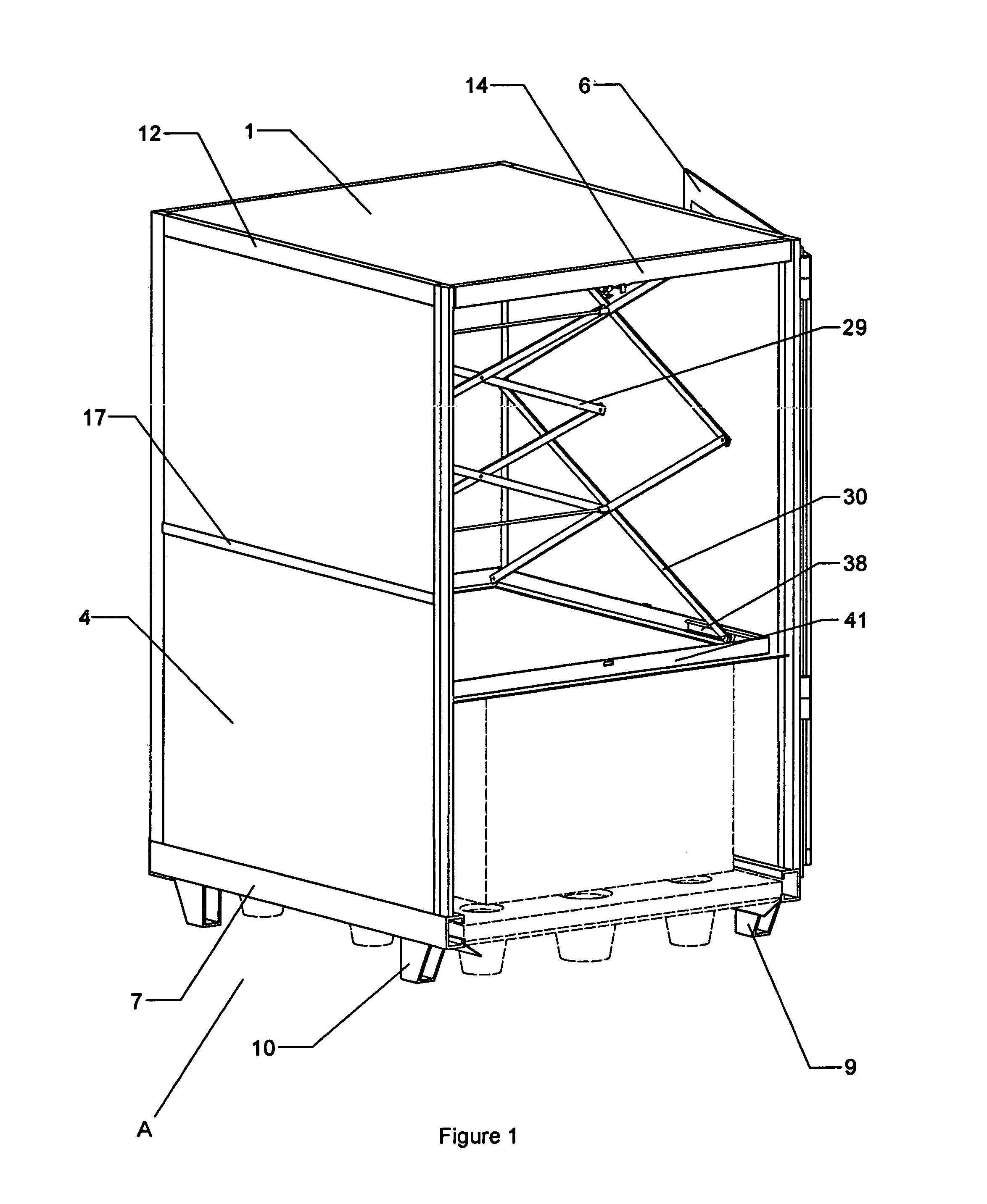
[0045]Now referring to the drawing, and in particular to FIGS. 1 to 12, a reducer of cold room (B) according to the illustrated mode of realization preferred of the invention is intended to be used for reducing the space preserving the frozen foods either by using the ice bags or dry ice during the delivery of the frozen foods.

[0046]Referring mainly to FIGS. 1 to 10, it is shown a cage (A) in which is mounted the reducer (B), and which includes an insulating panel (1) that is engaged inside each tubular member (11)(12)(14)(16), and which the tubular member (14) is provided with a hook that allows the reducer of cold room mounted inside the cage to be manually blocked when the hook is engaged in an opening formed therethrough a tubular member (41) which is connected to each tubular member (37) and to a tubular member (40) for receiving a vapor barrier (42), a rubber foam (43) and a rigid sheet (44). An insulating panel (4) which is engaged inside each tubular member (7)(12) and betwe...


PUM


Abstract

A cage in which is mounted a reducer of cold room that can be manually raised and blocked during the loading or unloading of the goods, and that automatically slopes down above the frozen foods when the door is closed for reducing the space preserving the frozen foods either by using the ice bags or dry ice during the delivery of the frozen foods.

Description

BACKGROUND OF THE INVENTION[0001]1. Field of the Invention[0002]More particularly, this invention refers to a cage in which is mounted a reducer of cold room that automatically slopes down above the frozen foods when the door is closed for reducing the space preserving the frozen foods either by using the ice bags or dry ice during the delivery of the frozen foods.[0003]2. Description of the Related Art[0004]A search of prior art records has unveiled the following patents:[0005]1. U.S. 2003 / 0014994 A1 registered in 2002 to Smith and al.;[0006]2. U.S. Pat. No. 4,947,658 issued in 1990 to Wheeler and al.;[0007]3. EP 0,7118,212 A1 issued in 1996 to Hazley and al.;[0008]4. U.S. Pat. No. 4,407,144 issued in 1983 to Garside;[0009]5. U.S. Pat. No. 4,682,708 issued in 1987 to Pool; and[0010]6. U.S. Pat. No. 4,921,105 issued in 1990 to Culbreth.[0011]The patents of Smith, Wheeler, Hazley, Garside, Pool and Culbreth are probably the most relevant.[0012]In the current market the cages are know...

Claims


Application Information

Patent Timeline
Patent Type & Authority Patents(United States)
IPC IPC(8): B65D6/16F25D3/02F25D3/12F25D3/00F25D23/06
CPCF25D3/00F25D23/069F25D2400/16
Inventor RENAUD, ALAIN
Owner RENAUD ALAIN
Features
  • R&D
  • Intellectual Property
  • Life Sciences
  • Materials
  • Tech Scout
  • Unparalleled Data Quality
  • Higher Quality Content
  • 60% Fewer Hallucinations
Learn More