Supercharge Your Innovation With Domain-Expert AI Agents!

Programmable passive inductor

a passive inductor and programmable technology, applied in the field of programmable passive inductor, can solve the problems of degraded noise performance, complex circuit, active inductors, etc., and achieve the effect of effective inductan

Inactive Publication Date: 2006-02-28
SCINTERA NETWORKS
View PDF5 Cites 3 Cited by
  • Summary
  • Abstract
  • Description
  • Claims
  • Application Information

AI Technical Summary

Benefits of technology

This approach enables flexible and efficient adjustment of inductance in high-speed circuits, enhancing performance by maintaining high Q factors and adaptability, suitable for applications like broadband amplifiers and filters, with improved robustness and design flexibility.

Problems solved by technology

However, with many applications, as the frequency of operation of a device increases, the circuit becomes more complicated, and narrow variation and strict tolerance are required for the components to operate properly.
However, active inductors have several disadvantages, including degraded noise performance, higher distortion, relatively high power requirements, lower quality or Q factor (i.e., the relative absence of resistive losses) than passive inductors, and limited dynamic range.
In addition, active inductors are limited in their operation to lower speeds and are not capable of providing variable inductance at high speed.
However, changing the inductance of passive inductors is often burdensome.
However, the use of many taps may also result in the formation of undesirable parallel resonance circuits and a lowered overall Q factor for the circuit, thereby reducing the sharpness of the circuit response at the selected frequency.

Method used


Image

  • Programmable passive inductor
  • Programmable passive inductor
  • Programmable passive inductor

Examples


Embodiment Construction

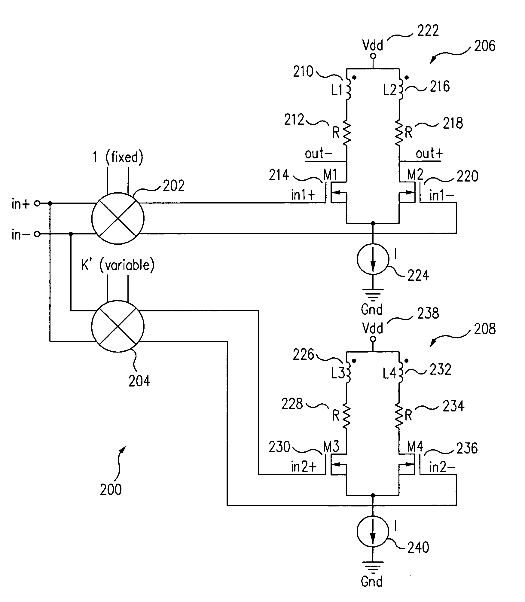
[0015]According to one aspect of the invention, the inductance of an inductor circuit is changed by varying the magnitude of a current through one of the two inductor coils, where the two inductor coils are coupled to form a transformer. The change in current changes the effective inductance of the circuit.

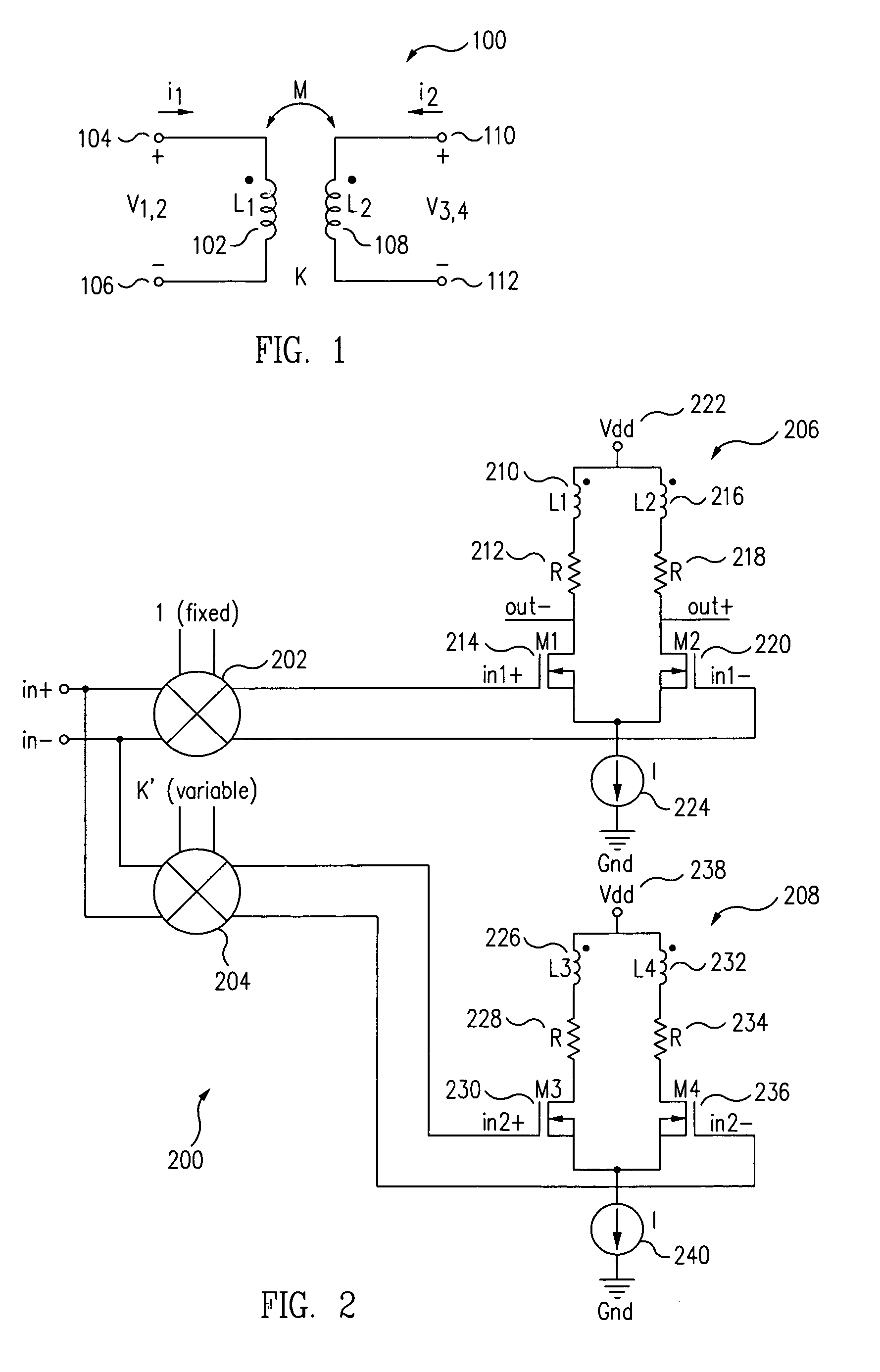
[0016]FIG. 1 shows a programmable or variable passive inductor 100 according to one embodiment. Programmable inductor 100 includes a first inductor 102 having a first end 104 and a second end 106 and a second inductor 108 having a first end 110 and a second end 112. In one embodiment, first and second inductors 102 and 108 are coiled conductive wires. First inductor 102 has a self inductance L1, and second inductor 108 has a self inductance L2. Current i1 flows through primary or first inductor 102 from first end 104 to second end 106, while a current i2 flows through secondary or second inductor 108 from first end 110 to second end 112. The mutual inductance M between first induc...


PUM


Abstract

A programmable passive inductor includes two inductors or coils, each having a self-inductance, magnetically coupled together and having a mutual inductance proportional to a magnetic coupling factor. The relative magnitude of the currents through the two inductors can be dynamically varied, which changes the effective inductance.

Description

[0001]This application is a divisional of U.S. patent application Ser. No. 10 / 698,317, filed Oct. 30, 2003, which is herein incorporated by references for all purposes.BACKGROUND[0002]1. Field of the Invention[0003]The present invention relates to inductor circuits, and in particular, to such circuits that allow variable inductances.[0004]2. Related Art[0005]As is well known, inductors generate an electromotive force by changing the current flowing through the inductor. In its simplest form, an inductor is a coiled conducting wire with N number of turns. Inductors can be used in a wide range of applications, such as for impedance matching and loading in low noise amplifiers, broadband amplifiers, power amplifiers, mixers and analog filters, as well as for providing frequency-selective resonant circuits in variable-frequency oscillators in such RF-wireless products. However, with many applications, as the frequency of operation of a device increases, the circuit becomes more complica...

Claims


Application Information

Patent Timeline
Patent Type & Authority Patents(United States)
IPC IPC(8): H03F3/45H03H11/48
CPCH03F3/45183H03F2203/45638H03H11/48H03F2203/45731H03F2203/45702
Inventor MUKHERJEE, DEBANJANBHATTACHARJEE, JISHNU
Owner SCINTERA NETWORKS
Features
  • R&D
  • Intellectual Property
  • Life Sciences
  • Materials
  • Tech Scout
  • Unparalleled Data Quality
  • Higher Quality Content
  • 60% Fewer Hallucinations
Learn More