
Software protection device and method

Inactive Publication Date: 2006-04-04
SAFENET
View PDF28 Cites 27 Cited by
  • Summary
  • Abstract
  • Description
  • Claims
  • Application Information

AI Technical Summary

Benefits of technology

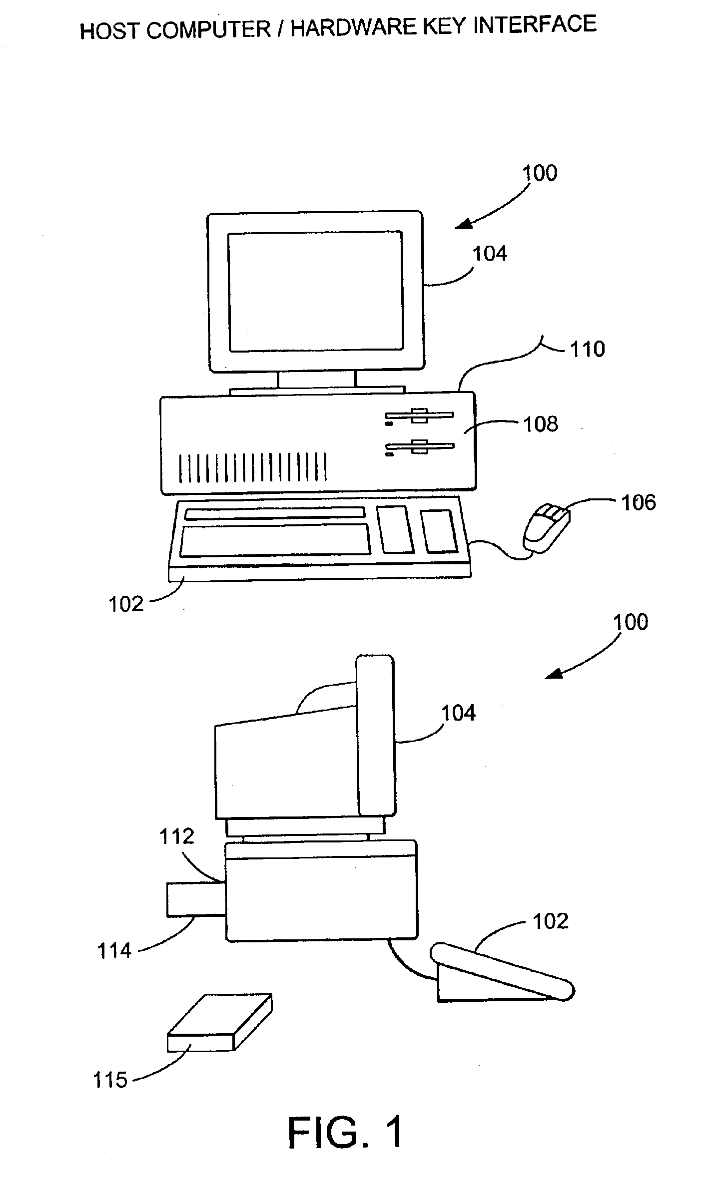
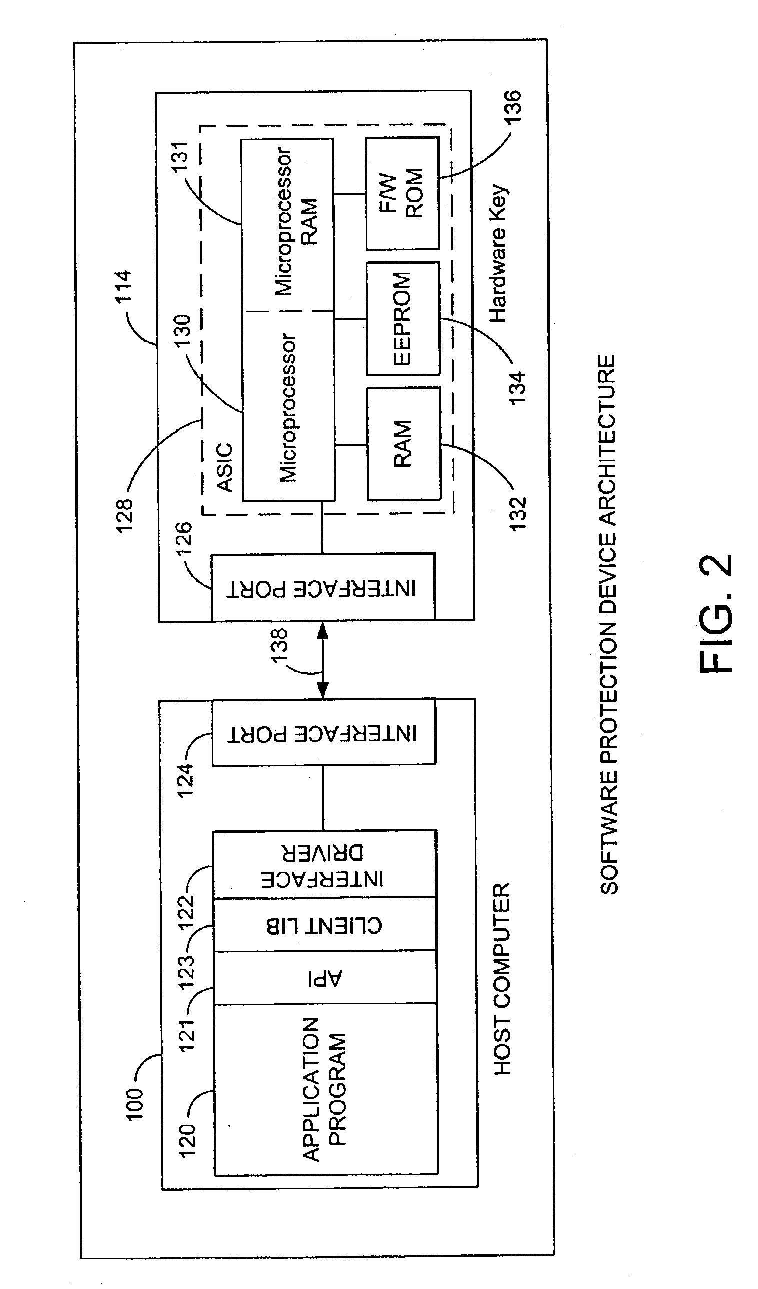
[0013]The apparatus comprises a hardware key with a communicating means coupled to the computer for receiving command messages and providing response messages to the computer, a memory for storing data used in translating command messages into response messages to enable execution of software on the computer, and a processor coupled to the communicating means and the memory. The processor includes a means for interpreting command messages to generate processor command functions, a translator for generating response messages from the processor commands, and a memory manager to protect data from unauthorized access. The memory manager logically segments the memory into at least one protected segment and controls access to this protected segment. This is accomplished with an instruction mapper which selectively maps processor commands to memory address locations. The hardware key also employs a means for decrypting coded software and performing the decrypted instructions, and supports encrypted communications between the hardware key and the host computer. Additional capabilities are provided by programming interface module, command class dispatcher, and a license manager. The programming interface module allows secure programming of the hardware key without compromising its contents. The command class dispatcher provides for backwards compatibility of the present invention with other software protection devices. The license manager allows a software developer to use the hardware key to implement secure licensing schemes.

Problems solved by technology

The growing use of computers has resulted in extensive unauthorized use and copying of computer software, costing software developers substantial revenue.
Although unauthorized copying of computer software is a violation of the law, the widespread availability of pirated software and enforcement difficulties have limited the effectiveness of this means of preventing software piracy.
While the Chorley device makes unauthorized access to the keys by the dongle processor difficult, it also prevents authorized access at any other time, and does not allow the memory in which the keys are stored to be used for other purposes.
Also, the Chorley device is still not impervious to software piracy, because the unencrypted software module is eventually stored in the hardware key in an unprotected memory, where it can be accessed by the host computer.
This may be prevented by enforcing encrypted and decrypted communications between the host computer and the dongle, such as disclosed in U.S. Pat. No. 4,596,898, issued on Jun. 24, 1986, to Permmaraju or U.S. Pat. No. 4,864,494, issued on Sep. 5, 1989, to Kobus, but this cannot be implemented with the Chorley device, because access to the keys is temporally limited.
However, the Chandra and Nolan devices have practical limitations which limit their usefulness to prevent software piracy.
The Chandra and Nolan devices also do not permit flexible access to other portions of the RAM which do not contain sensitive data.
Because the Chandra device must be usable with a wide variety of software applications, it must employ an “open architecture,” and to prevent unauthorized access to sensitive information, is incapable of acquiring and transferring the right to execute the protected software.
However, using two separate processors unnecessarily complicates the design and provides the potential software hacker with more opportunities to circumvent the software protection schemes employed in the device.
Another problem with current software protection devices is that they are not backwards-compatible, and are not flexible enough to implement a wide variety of software protection algorithms within a single hardware key.
Prior art software protection devices are incapable of supporting both of these software protection schemes, and two hardware keys would be required.

Method used


Image

  • Software protection device and method
  • Software protection device and method
  • Software protection device and method

Examples


Embodiment Construction

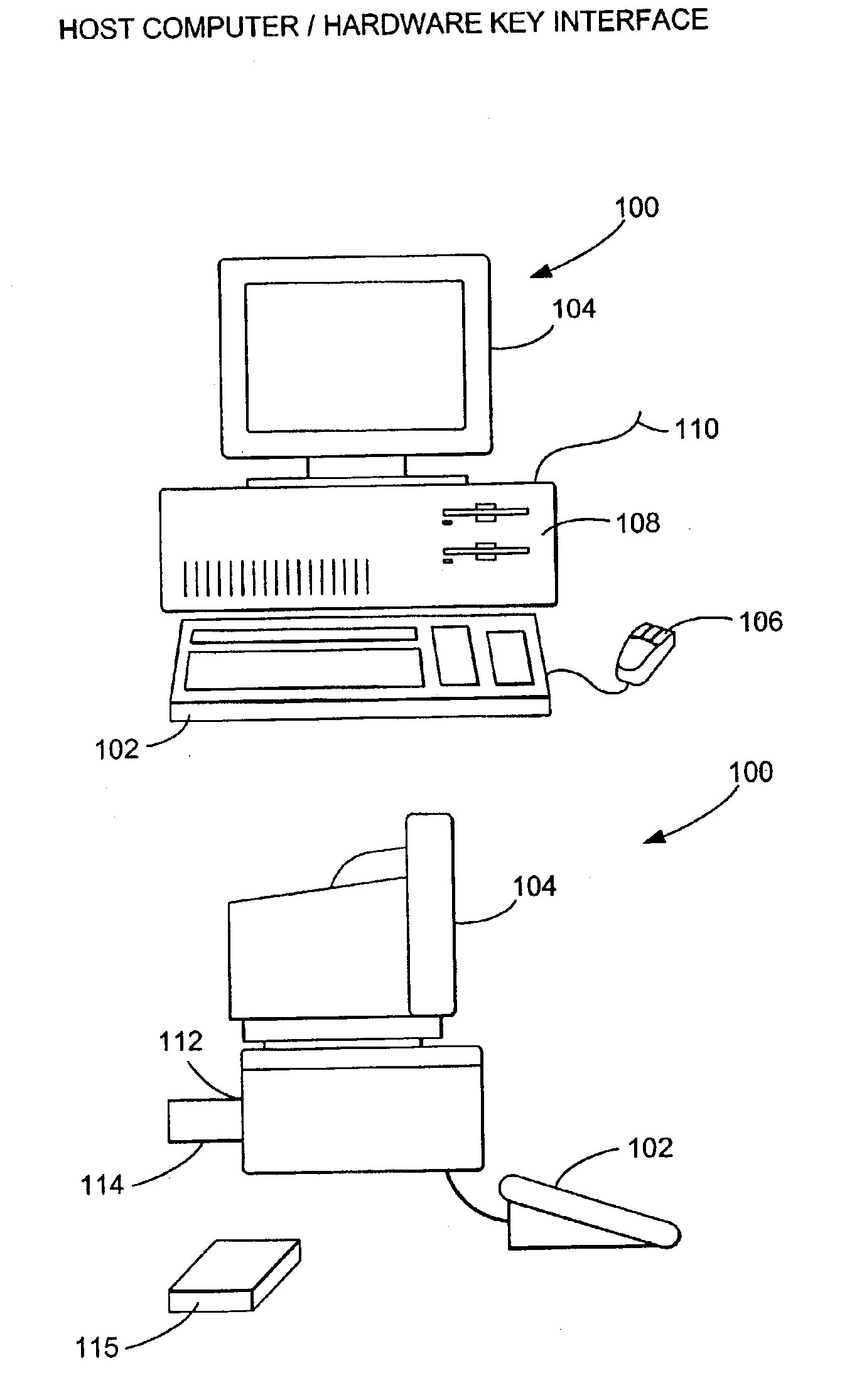
[0025]In the following description of the preferred embodiment, reference is made to the accompanying drawings which form a part hereof, and which is shown by way of illustration a specific embodiment in which the invention may be practiced. It is understood that other embodiments may be utilized and structural changes may be made without departing from the scope of the present invention.

Overview

[0026]The present invention provides a high degree of security and flexibility to protect software in both stand-alone and networked applications enabling users to develop a single security strategy, using a common Application Program Interface (API) for both stand-alone and networked applications across all platforms. It features a cross-platform API, allowing software developers to easily port software across a wide variety of platforms. The present invention supports all current parallel printer ports, RS-232 and RS-423 serial ports, and Macintosh™ Apple Desktop Bus (ADB) ports, thus prov...


PUM


Abstract

A method and apparatus for protecting computer software from unauthorized execution or duplication using a hardware key is disclosed. The apparatus comprises a means for communicating with the computer to receive command messages from the computer in the hardware key and to provide response messages to the computer, a memory for storing data for translating command messages into response messages enabling software execution, and a processor coupled to the communicating means for translating command messages into response messages using the data stored in the memory. The processor further comprises a memory manager, including means for logically segmenting the memory storing the data into at least one protected segment, and a means for controlling access to the protected segment.

Description

CROSS-REFERENCE TO RELATED APPLICATIONS[0001]This application is a continuation of U.S. patent application Ser. No. 08 / 760,648, entitled “SOFTWARE PROTECTION DEVICE AND METHOD,” by Dominique V. Pavlin, Mehdi Sotoodeh, Reed H. Tibbetts, Patrick N. Godding, Alain R. Spiewek, and Roger G. Nixon, filed Dec. 4, 1996, now U.S. Pat. No. 6,523,119 which application is hereby incorporated by reference herein.BACKGROUND OF THE INVENTION[0002]1. Field of Invention[0003]The present invention relates generally to devices and methods for protecting computer software and in particular to devices and methods for protecting software by secure transmission and execution of encrypted software in a hardware key.[0004]2. Description of Related Art[0005]In the last decade, the use of computers in both the home and office have become widespread. The growing use of computers has resulted in extensive unauthorized use and copying of computer software, costing software developers substantial revenue. Althoug...

Claims


Application Information

Patent Timeline
IPC IPC(8): H04L9/32G06F12/00G06F9/45H04L9/00G06F1/00G06F21/00
CPCG06F21/123G06Q20/0855Y10S707/99956Y10S707/99953
Inventor PAVLIN, DOMINIQUE VINCENTSOTOODEH, MEHDITIBBETTS, REED H.GODDING, PATRICK N.SPIEWEK, ALAIN RAYMONDNIXON, ROGER GRAHAM
Owner SAFENET
Learn More