Check patentability & draft patents in minutes with Patsnap Eureka AI!

X-ray apparatus for intraoral imaging applications

a technology for intraoral imaging and x-ray apparatus, which is applied in the direction of x-ray apparatus, electrical apparatus, medical science, etc., can solve the problems of increased costs for the manufacturer and new arm members, and achieve the effect of saving total costs

Inactive Publication Date: 2006-04-18
PALODEX GROUP
View PDF4 Cites 14 Cited by
  • Summary
  • Abstract
  • Description
  • Claims
  • Application Information

AI Technical Summary

Benefits of technology

This solution simplifies the redesign of the linkage, reduces manufacturing and stocking costs, and allows for easy adjustments in the X-ray apparatus without the need for multiple arm lengths, thereby lowering operational and manufacturing expenses.

Problems solved by technology

One problem in such a prior art X-ray arrangement for intraoral applications relates to varying space arrangements in facilities where the apparatus is to be used, whereby the linkage supporting the X-ray source must be dimensioned for a particular site, making it necessary for the linkage to have arms of various lengths.
Such ordering and replacement of a new arm member incurs extra costs for the operator.
In addition, there will be costs for the manufacturer caused by manufacturing and stocking arm members of various lengths.

Method used


Image

  • X-ray apparatus for intraoral imaging applications
  • X-ray apparatus for intraoral imaging applications
  • X-ray apparatus for intraoral imaging applications

Examples


Embodiment Construction

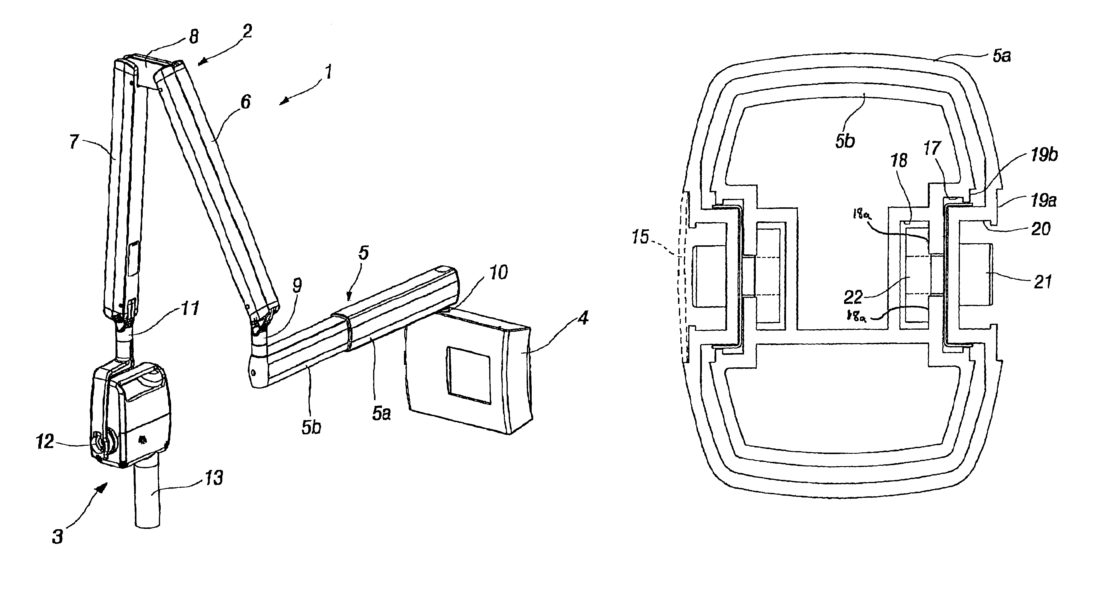
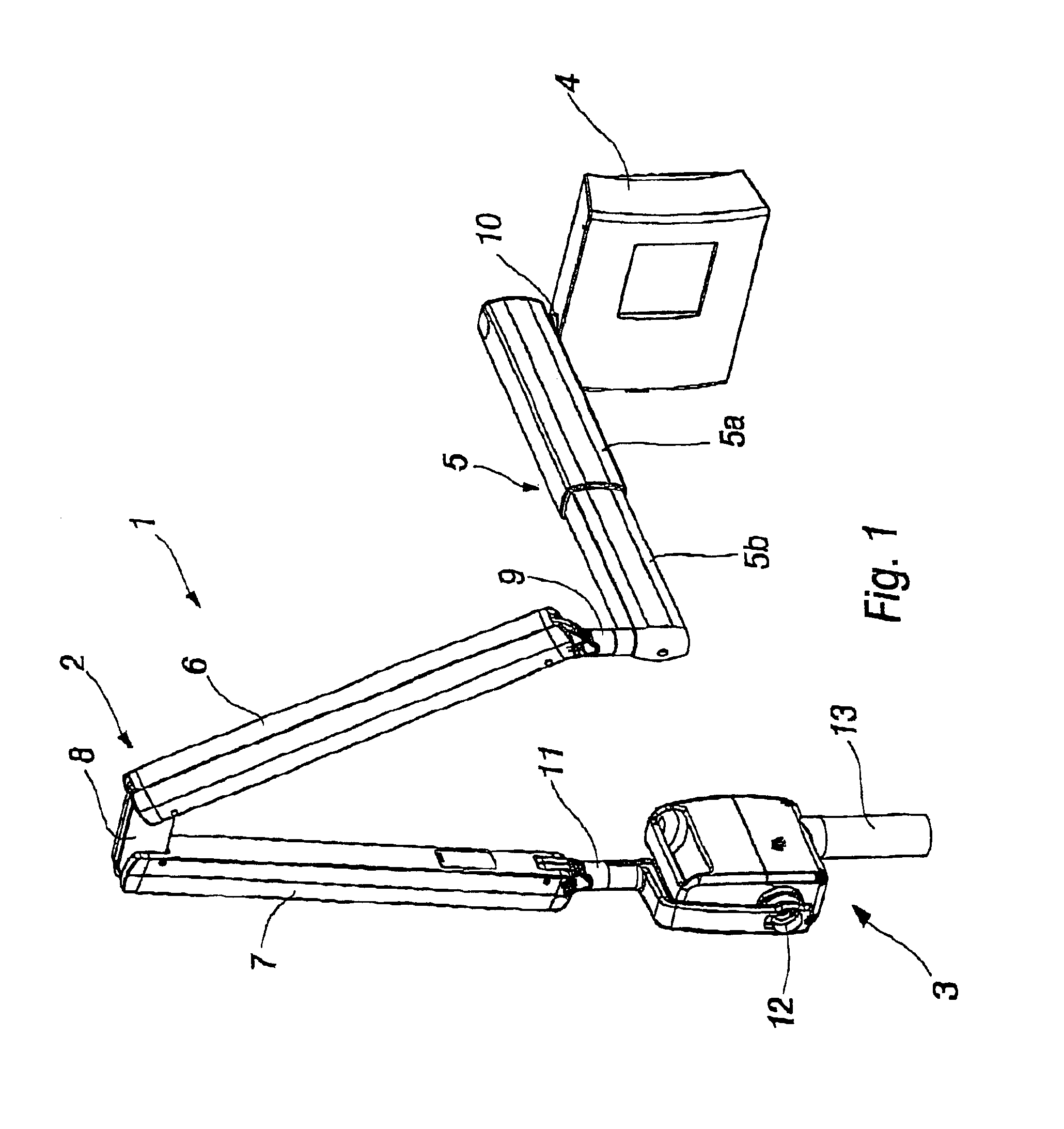
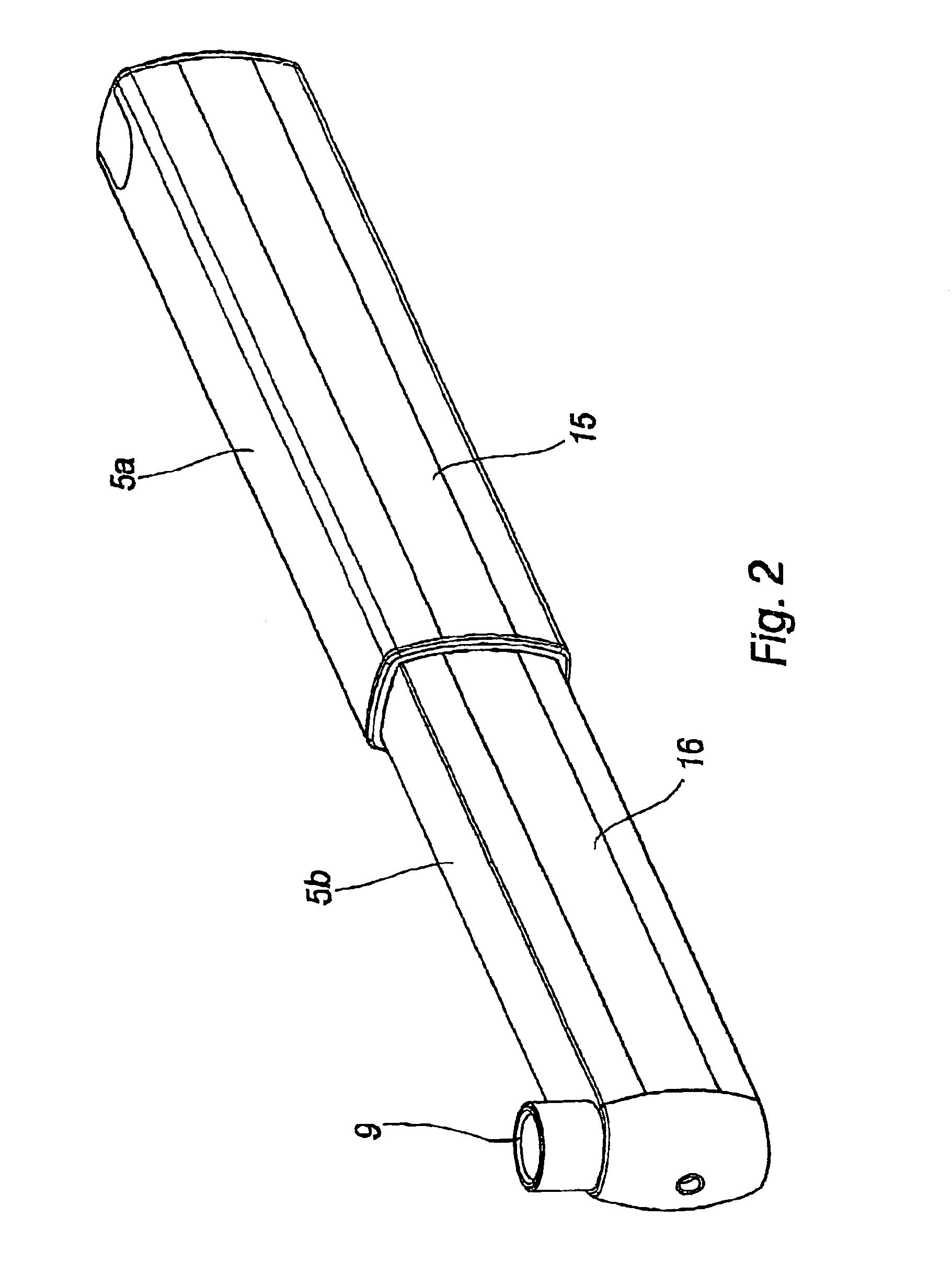
[0016]In reference to FIGS. 1-5, an X-ray apparatus 1 of the invention for intraoral imaging applications includes a first arm member 5, mounted on a support structure 4 and pivotable about a vertical axle 10 in a substantially horizontal plane, which comprises two telescopically fitted arm sections 5a, 5b. It has been proposed that the distal end of the arm 5 be provided with an arm member 6, adapted to be pivotable around a substantially vertical pivoting axle at an articulation 9 and having its opposite distal end fitted by means of a link element 8 with a third arm member 7, pivotable relative to the link element 8 around a substantially horizontal axis. To the distal end of the arm 7 is connected, by way of an articulated joint 11, an X-ray source 3 which is rotatable to various positions about a vertical axis in the articulated joint 11, as well as around a horizontal axle 12. The X-ray source 3 includes further a tube element 13 for emitting radiation in a desired direction.

[...


PUM


Abstract

An x-ray apparatus for intraoral imaging applications includes a linkage mounted on a support structure, to which is connected an x-ray source for generating x-radiation and directing same to a receiver instrument placed in a patient's mouth. The linkage includes a first arm member, articulated to the support structure and adapted to be pivotable about a substantially vertical axis, a second arm member, connected to the end of the first arm member spaced from the support structure and adapted to be pivotable around a substantially vertical axis and a horizontal axis, and a third arm member, connected to the opposite end of the second arm member and adapted to be pivotable around a substantially horizontal axis, the unsupported end of the latter having the x-ray source mounted thereon with an articulated joint, which allows pivoting of the x-ray source to various positions.

Description

[0001]In dentistry, taking X-ray images of the teeth and jawbone structure is important for a reliable and successful examination of the teeth and jawbone structure. Intraoral applications are performed by using an intraorally placed X-ray detector for the reception of X-radiation. The X-radiation is emitted from an X-ray source outside the mouth to a point in the teeth and jaw structure to be examined.PRIOR ART[0002]The X-ray detector is typically placed in the mouth by using special retainers. The object to be imaged is irradiated with X-radiation, which is produced by an extraoral X-ray source. The X-radiation that has passed through the object is received by an X-ray detector. Positioning of the X-ray detector in the mouth and alignment of X-radiation can be varied for imaging various parts of the teeth and jaw structure.[0003]FIG. 6 illustrates one X-ray arrangement for use in intraoral application, which is described in the present assignee's earlier U.S. Pat. No. 6,898,268. T...

Claims


Application Information

Patent Timeline
Patent Type & Authority Patents(United States)
IPC IPC(8): H05G1/02A61B6/51
CPCA61B6/145A61B6/512
Inventor MARTTI, JUHANIIHALAINEN, PEKKA
Owner PALODEX GROUP
Features
  • R&D
  • Intellectual Property
  • Life Sciences
  • Materials
  • Tech Scout
  • Unparalleled Data Quality
  • Higher Quality Content
  • 60% Fewer Hallucinations
Learn More