Supercharge Your Innovation With Domain-Expert AI Agents!

Heat dissipation device for electronic device

a technology for electronic devices and heat dissipation devices, which is applied in the direction of lighting and heating apparatus, semiconductor/solid-state device details, instruments, etc., can solve the problems of reducing the heat dissipation efficiency of electronic devices, affecting the operation stability of electronic devices, and significantly limiting the height of formed fins. , to achieve the effect of efficient dissipation of heat from electronic devices

Inactive Publication Date: 2006-06-06
HON HAI PRECISION IND CO LTD
View PDF12 Cites 10 Cited by
  • Summary
  • Abstract
  • Description
  • Claims
  • Application Information

AI Technical Summary

Benefits of technology

The design improves heat transfer efficiency by aligning airflow with spiral passages and positioning fan supports outside the passages, facilitating better cooling and reducing thermal resistance.

Problems solved by technology

Electronic devices such as central processing units (CPUs) generate a lot of heat during normal operation.
If the heat generated is not properly dissipated, it can deteriorate their operational stability and damage associated electronic devices.
A conventional heat dissipation device is made by extrusion, which significantly limits the height of its formed fins.
However, because the fins are adhered to the base air gap inevitablely exists between the base and the fins.
This reduces heat transmit efficiency from the base to the fins.
These obstructs the air flow of the fan flowing through the fins and limits heat dissipation of the fins, thereby reducing the efficiency of heat transfer of the heat dissipation device.
However, a mounting plate on which a fan is mounted is stilled fixed on a top of a cylindrical core of the heat dissipation device between the fan and the fins, which obstructs the air flow of the fan flowing through the fins and limits heat dissipation of the fins, thereby reducing the efficiency of heat transfer of the heat dissipation device.

Method used


Image

  • Heat dissipation device for electronic device
  • Heat dissipation device for electronic device
  • Heat dissipation device for electronic device

Examples


Embodiment Construction

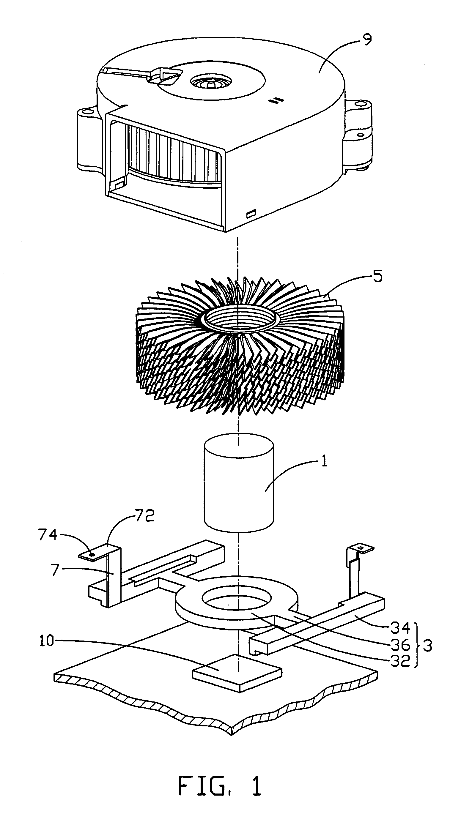
[0018]Referring to FIGS. 1–3, a heat dissipation device in accordance with the preferred embodiment of the present invention comprises a cylindrical column 1 for being positioned on an electronic device 10, a securing member 3 for securing the heat dissipation device to the electronic device 10, a plurality of fin units 5 attachably surrounding the column 1, a pair of fan supports 7 extending from the securing member 3, and a fan 9 mounted on the fan support 7.

[0019]The column 1 is made of heat conductive material such as copper or aluminum. The column 1 may be a solid column or a hollow heat pipe filled with coolant.

[0020]The securing member 3 is generally H-shaped and comprises a base 32, a pair of securing bars 34, and a pair of connecting bars 36 connected the base 32 and the securing bars 34. The base 32 is circular shape and defines a central through hole (not labeled) for extension of the column 1 therethrough. The column 1 is fixed in the through hole of the base 32 by weldi...


PUM


Abstract

A heat dissipation device includes a column (1) for being positioned on an electronic device for dissipating heat therefrom, a plurality of fin units (5) attached to and stacked along the column, an H-shaped securing member (3) attached to the column below the fin units for securing the heat dissipation device to the electronic device, a pair of fan supports (7) extending from opposite sides of the securing member, and a fan (9) mounted on the fan supports. The fin units define a plurality of sprial air passages along an axis of the column which consist with air flow of the fan. Each of the fin units is configured by a metal disc with a plurality of sectors (54, 54′, 54″) and channels (56, 56′, 56″) between adjacent sectors.

Description

BACKGROUND OF THE INVENTION[0001]1. Field of the Invention[0002]The present invention relates to a heat dissipation device for electronic devices, and particularly to a heat dissipation device incorporating a plurality of stacked fins.[0003]2. Related Art[0004]Electronic devices such as central processing units (CPUs) generate a lot of heat during normal operation. If the heat generated is not properly dissipated, it can deteriorate their operational stability and damage associated electronic devices. Thus the heat must be removed quickly and efficiently to ensure normal operation. A heat dissipation device is often attached to a top surface of a CPU, to remove heat therefrom.[0005]A conventional heat dissipation device is made by extrusion, which significantly limits the height of its formed fins. To resolve the problem, another kind of heat dissipation device has been developed. Fins of such device are folded from a metal sheet. The folded fins are then adhered to a base which is ...

Claims


Application Information

Patent Timeline
Patent Type & Authority Patents(United States)
IPC IPC(8): F28F7/00G06F1/16G06F1/20H01L23/34H01L23/467H05K7/20
CPCH01L23/467H01L2924/0002H01L2924/00
Inventor WANG, YAXIONGDONG, SHUN CHIHUANG, CHUNG-YUAN
Owner HON HAI PRECISION IND CO LTD
Features
  • R&D
  • Intellectual Property
  • Life Sciences
  • Materials
  • Tech Scout
  • Unparalleled Data Quality
  • Higher Quality Content
  • 60% Fewer Hallucinations
Learn More