Check patentability & draft patents in minutes with Patsnap Eureka AI!

Wall recessed outlet box assembly

a technology for outlet boxes and wall recessed outlets, which is applied in the direction of machine supports, coupling device connections, mechanical devices, etc., can solve the problem of reducing the likelihood of the cable plug being contacted by an external force, and achieve the effect of reducing the likelihood of the electrical plug being contacted

Active Publication Date: 2006-07-18
THOMAS & BETTS INT INC
View PDF45 Cites 43 Cited by
  • Summary
  • Abstract
  • Description
  • Claims
  • Application Information

AI Technical Summary

Benefits of technology

The solution effectively reduces the risk of plug and cable exposure to external forces, enhances stability by securing the receptacle within the housing, and allows for the placement of objects closer to the wall without obstructing the view of cables and plugs, improving safety and aesthetics.

Problems solved by technology

The recess of the communication port results in the cable plug being recessed which reduces the likelihood of the cable plug being contacted by an external force.

Method used


Image

  • Wall recessed outlet box assembly
  • Wall recessed outlet box assembly
  • Wall recessed outlet box assembly

Examples


Embodiment Construction

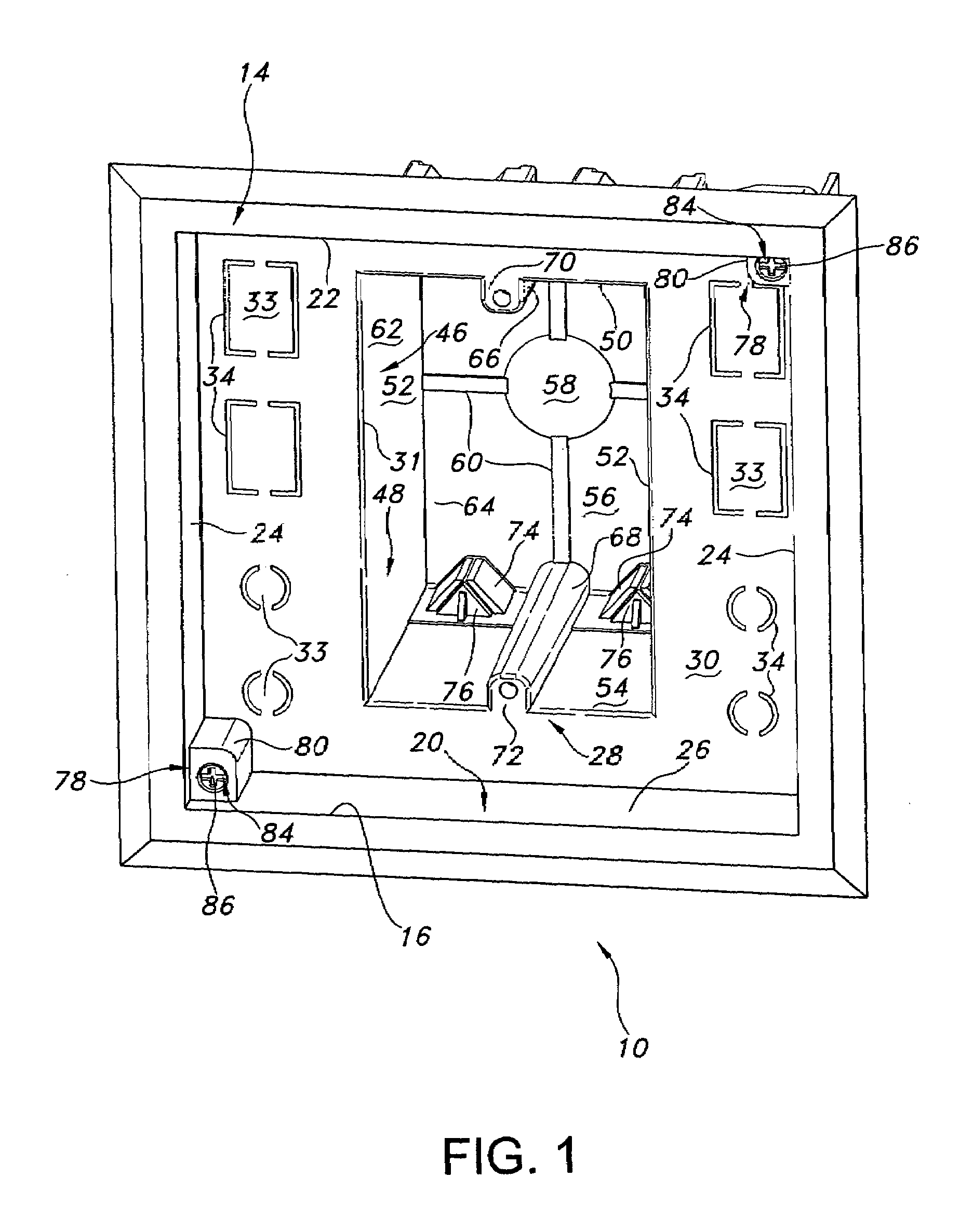
[0033]Referring to the drawings and more particularly to FIGS. 1 to 7, a wall recessed outlet box assembly 10 is shown for mounting to a wall structure 12, such as the vertical wall board of an interior wall of a building structure.

[0034]The outlet box assembly 10 includes an outer faceplate 14 which has an interior opening 16 and a rear surface 18. The outer faceplate 14 is planar and has an outer edge which may be beveled.

[0035]A flange structure 20 is fixed to the rear surface 18 and has a top flange 22, a pair of side flanges 24, and a bottom flange 26 which are fixed to one another such that each of the side flanges is between the top and bottom flanges in perpendicular relation thereto. This results in the flange structure 20 having a vertical cross-section which is rectangular.

[0036]The outlet box assembly 10 includes an inner faceplate 28 having a front surface 30 which is fixed to the rear edges of the flange structure 20 such that the inner faceplate is recessed from the o...


PUM


Abstract

An outlet box assembly includes an outer faceplate having an interior opening. An inner faceplate is connected to the outer faceplate such that the inner faceplate is recessed from the outer faceplate and access to the inner faceplate is provided through the interior opening. The inner faceplate has an outlet port and a communication port. The outlet box assembly further includes a support housing having an inner surface and an interior region bounded by the inner surface. The support housing is connected to a rear surface of the inner faceplate such that the outlet port provides access to the interior region. The support housing is configured to allow insertion of an electrical receptacle into the interior region and to provide an enclosure for the electrical receptacle.

Description

CROSS-REFERENCE TO RELATED APPLICATIONS[0001]This patent application claims priority to and the benefit of U.S. Provisional Patent Application No. 60 / 572,276 filed in the U.S. Patent and Trademark Office (USPTO) on May 18, 2004, and U.S. Design patent application Ser. No. 29 / 205,607 filed in the USPTO on May 18, 2004, the entire disclosures of all of which are hereby incorporated by reference herein.BACKGROUND OF THE INVENTION[0002]The present invention relates generally to outlet boxes for mounting electrical outlets and connectors on wall structures, and more particularly, to such an outlet box in which the electrical outlet and connector is recessed from the wall structure.[0003]Electrical outlet boxes which support an electrical receptacle and a connector are known. Such outlet boxes may support the electrical receptacle in the plane of the outer surface of the wall structure. As a result, when a plug is inserted into the electrical receptacle which is so supported, the plug ext...

Claims


Application Information

Patent Timeline
Patent Type & Authority Patents(United States)
IPC IPC(8): H02G3/10H01R13/62H02G3/12
CPCH02G3/123H02G3/14Y10S248/906
Inventor DINH, CONG THANH
Owner THOMAS & BETTS INT INC
Features
  • R&D
  • Intellectual Property
  • Life Sciences
  • Materials
  • Tech Scout
  • Unparalleled Data Quality
  • Higher Quality Content
  • 60% Fewer Hallucinations
Learn More