Polyaxial drill guide

Active Publication Date: 2006-08-22
K2M
View PDF5 Cites 137 Cited by
  • Summary
  • Abstract
  • Description
  • Claims
  • Application Information

AI Technical Summary

Benefits of technology

[0022]More particularly, the rotatable mounting in this third embodiment is provided inasmuch as the walls of the socket have a curvature that matches the contour of the semi-spherical outer surface portion. The semi-spherical outer surface portion cannot be placed into or removed from the curvate socket without the application of force. For example, the socket is curvate (preferably ball-shaped) and the resting diameter of the semi-spherical outer surface portion is greater than the distal opening of the curvate socket and greater than the interior opening of the curvate socket. This prevents the semi-spherical outer surface portion from slipping out of the curvate socket once it is fitted therein.
[0023]In order to enable the semi-spherical outer surface portion to be seated in the curvate socket and removed therefrom, the semi-spherical outer surface

Problems solved by technology

Because the cervical spine is routinely subject to mechanical loads which cycle during movement, one of the primary concerns of physicians performing cervical plate implantation surgeries, as well as of the patients in whom the implants are placed, is the risk of screw pullout.
Screw pullout occurs when the cylindrical portion of the bone that surrounds the inserted screw fails.
A bone screw that is implanted perpendicular to the plate is particularly weak because the region of the bone that must fail for pullout to occur is only as large as the outer diameter of the screw threads.
This is undesirable, in that physicians often must inspect the vertebral bodies during the implantation procedure before making the decision as to which screw-in angle is the ideal.
By forcing the physician to chose from a limited set of angles, it

Method used


Image

  • Polyaxial drill guide
  • Polyaxial drill guide
  • Polyaxial drill guide

Examples


second embodiment

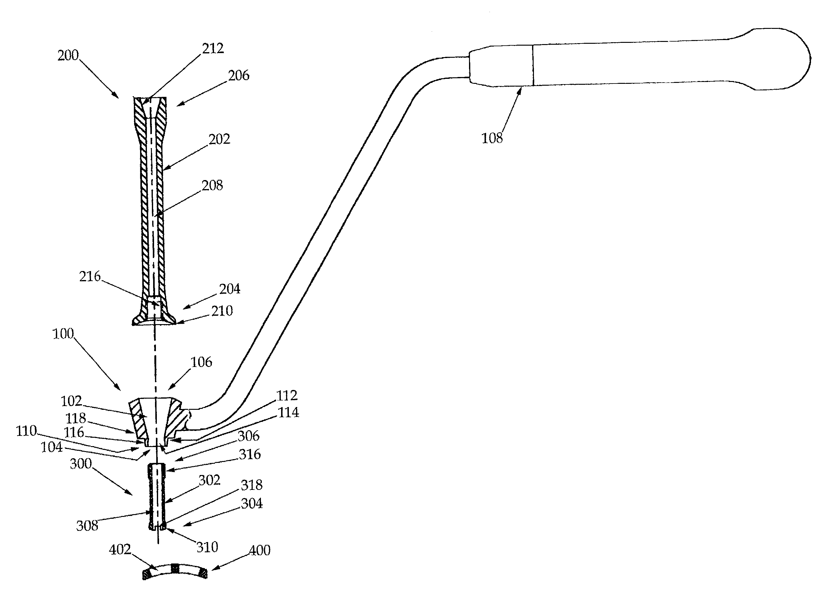
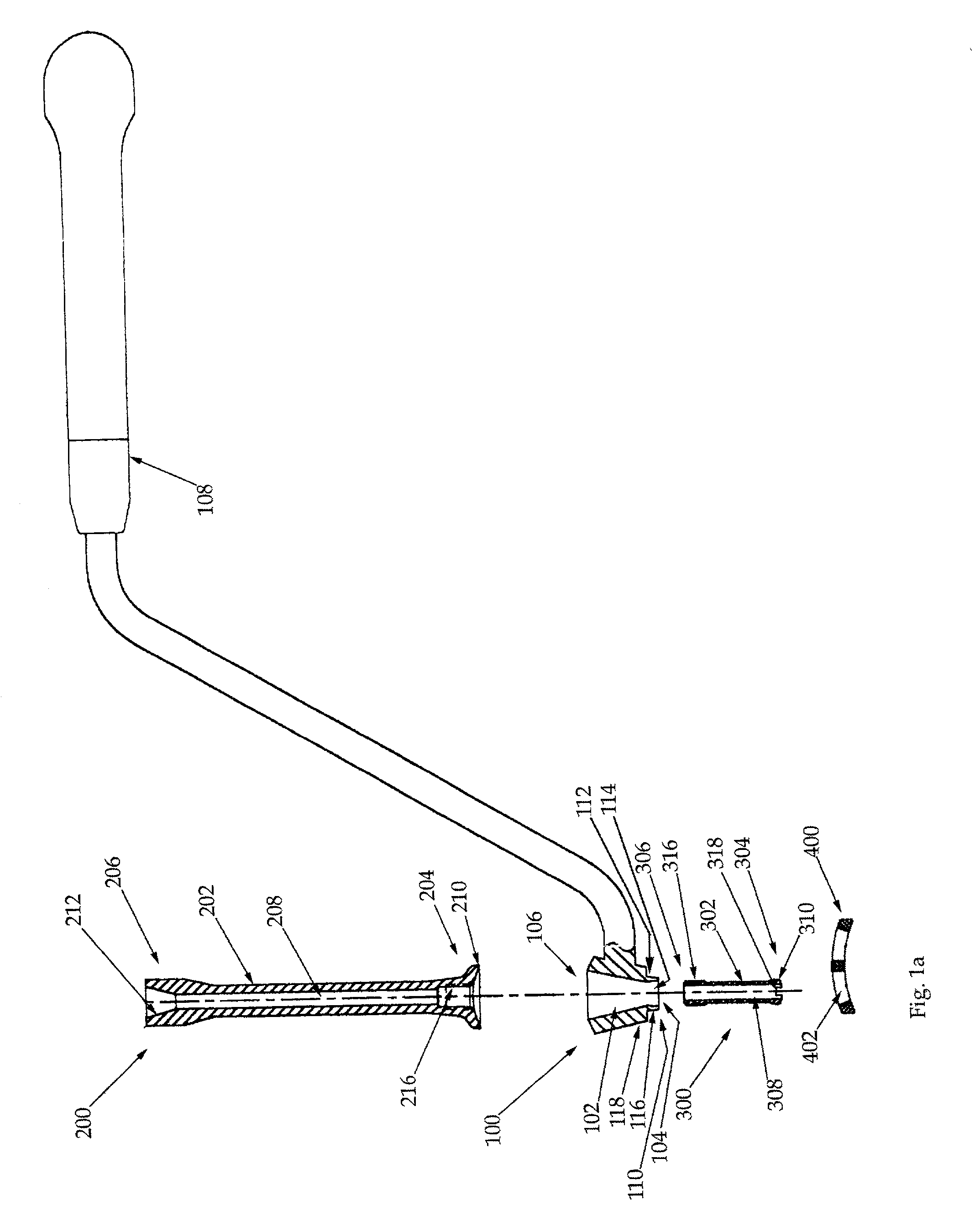
[0054]Each drill guide stem 200a, 200b includes a shaft 202a, 202b having a distal end 204a, 204b and a proximal end 206a, 206b and a longitudinal bore 208a, 208b having a diameter that accommodates the drill bit. Each stem shaft distal end 204a, 204b mounts to the associated collet shaft proximal end 306a, 306b such that each collet shaft longitudinal bore 308a, 308b is co-linear with the associated stem shaft longitudinal bore 208a, 208b. In this second embodiment, this co-linear mounting is provided inasmuch as each stem shaft longitudinal bore 208a, 208b has at the associated stem shaft distal end 204a, 204b an interior threading 216a, 216b and the associated collet shaft proximal end 306a, 306b has a corresponding outer threading 316a, 316b. Each inner threading 216a, 216b matches the corresponding outer threading 316a, 316b so that the threadings are mutually engageable. When each collet shaft proximal end 306a, 306b is screwed into the associated stem shaft distal end 204a, 2...

third embodiment

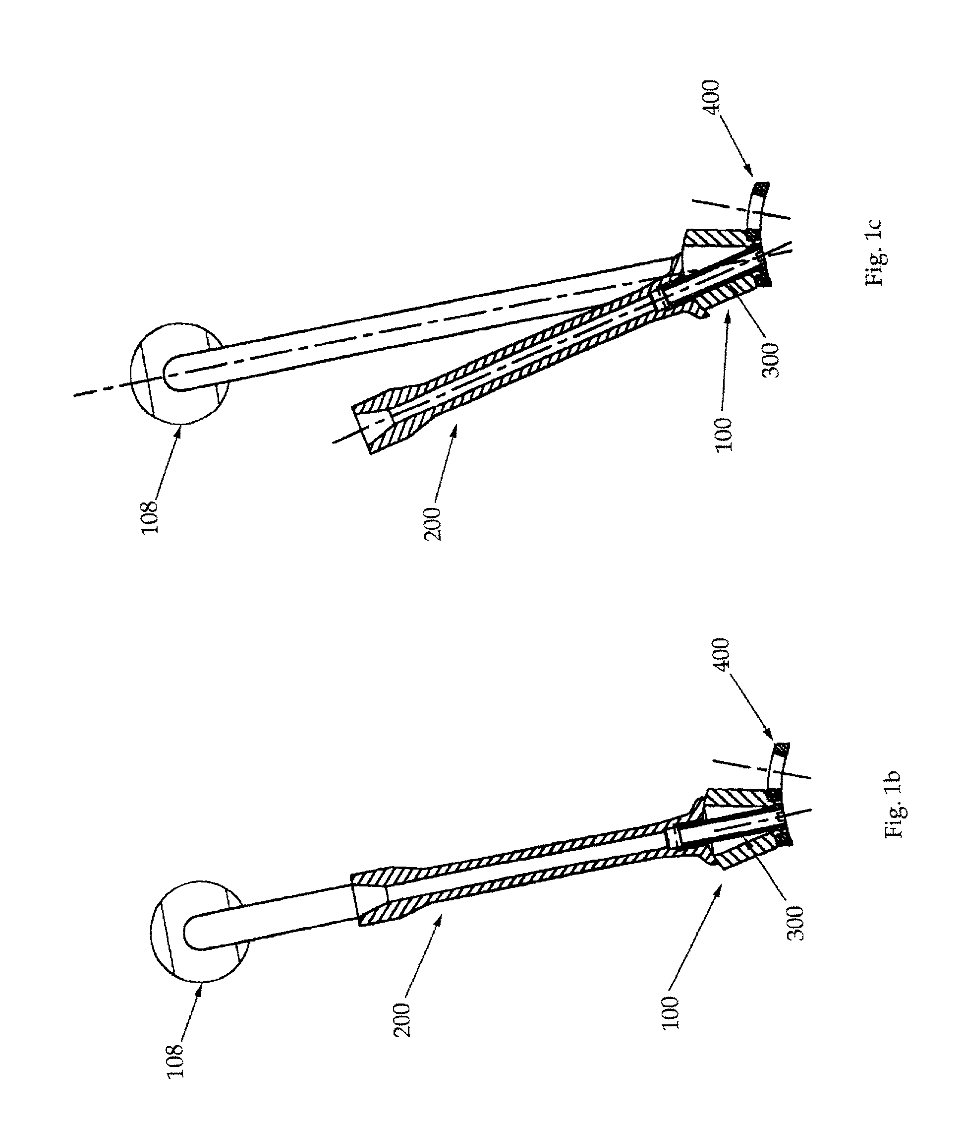
[0062]Referring now to FIGS. 3a–c, the invention includes a drill guide body 100 and a drill guide collet 300 (also referred to herein as a guide member).

[0063]The drill guide collet 300 includes a collet shaft 302 having distal and proximal ends 304, 306 and a longitudinal bore 308 having a diameter that accommodates a drill bit. The drill guide body 100 includes a conical bore 102 having narrow and wide ends 104, 106. The distal end 304 of the collet shaft 302 rotatably mounts within the narrow end 104 of the conical bore 102, with the collet shaft 302 extending toward the wide end 106 of the conical bore 102, such that the collet shaft 302 (and consequently the longitudinal bore 308) can be angled within the conical bore 102 at a plurality of angles with respect to the major axis of the conical bore 102. The conical angle of the conical bore 102 establishes the extent to which the collet shaft 302 can be angled.

[0064]The rotatable mounting is provided inasmuch as the narrow end 1...

fourth embodiment

[0074]In order to enable each semi-spherical outer surface portion 310a, 310b to be seated in the associated curvate socket 114a, 114b and removed therefrom, each semi-spherical outer surface portion 310a, 310b in the fourth embodiment is formed with a notch 312a, 312b that allows the semi-spherical outer surface portion 310a, 310b to be radially compressed under pressure to reduce its diameter enough to allow it to be passed through the distal opening (or, alternatively or additionally in other embodiments, the interior opening) of the associated curvate socket 114a, 114b. Once the pressure is released, the semi-spherical outer surface portion 310a, 310b returns to its resting diameter. Therefore, a force can be applied to press each semi-spherical outer surface portion 310a, 310b through the distal opening of the associated curvate socket 114a, 114b, causing the semi-spherical outer surface portion 310a, 310b to radially compress enough to pass through the associated distal openin...


PUM


Abstract

A polyaxial drill guide includes a body, a collet and a stem. The collet includes a collet shaft having distal and proximal ends and a longitudinal bore. The body includes a conical bore having narrow and wide ends. The distal end of the collet shaft rotatably mounts within the narrow end of the conical bore, with the collet shaft extending toward the wide end of the conical bore, such that the collet shaft (and consequently the longitudinal bore) can be angled within the conical bore at a plurality of angles. The stem includes a shaft having distal and proximal ends and a longitudinal bore. The distal end of the stem shaft mounts to the proximal end of the collet shaft such that the longitudinal bores are co-linear and a drill bit can be inserted into and rotated within the longitudinal bores during a drilling procedure.

Description

FIELD OF THE INVENTION[0001]This invention relates generally to drill guides and more specifically to a polyaxial drill guide for use in orthopedic surgery.BACKGROUND OF THE INVENTION[0002]The bones and connective tissue of an adult human spinal column consists of more than 20 discrete bones coupled sequentially to one another by a tri-joint complex which consist of an anterior disc and the two posterior facet joints, the anterior discs of adjacent bones being cushioned by cartilage spacers referred to as intervertebral discs. These more than 20 bones are anatomically categorized as being members of one of four classifications: cervical, thoracic, lumbar, or sacral. The cervical portion of the spine, which comprises the top of the spine, up to the base of the skull, includes the first 7 vertebrae. The intermediate 12 bones are the thoracic vertebrae, and connect to the lower spine comprising the 5 lumbar vertebrae. The base of the spine is the sacral bones (including the coccyx). Th...

Claims


Application Information

Patent Timeline
IPC IPC(8): A61B17/58A61B17/17
CPCA61B17/1728A61B17/1757
Inventor RALPH, JAMES D.TROXELL, THOMAS N.
Owner K2M
Why Eureka
Try Eureka