
Ceramic honeycomb filter and exhaust gas-cleaning method

a honeycomb filter and filter technology, applied in the direction of machines/engines, chemical/physical processes, metal/metal-oxide/metal-hydroxide catalysts, etc., can solve the problems of reducing the output of the engine, difficult to uniformly control the temperature inside the honeycomb filter, and long flow path direction, so as to prevent the breakage and melting of the filter, avoid the effect of pressure loss increase and stable us

Inactive Publication Date: 2006-09-19
HITACHI METALS LTD +1
View PDF16 Cites 25 Cited by
  • Summary
  • Abstract
  • Description
  • Claims
  • Application Information

AI Technical Summary

Benefits of technology

This design effectively prevents pressure loss increase and extends the filter's lifespan by ensuring continuous regeneration and uniform temperature control, allowing stable operation for a long period without breakage or melting.

Problems solved by technology

When particulates captured in the pores exceed a predetermined amount, the clogging of the pores takes place, causing the pressure loss of the honeycomb filter 1 to increase and thus resulting in decrease in an engine output.
In a case where particulates are burned and removed by a burner or an electric heater, the larger the amount of particulates captured, the more difficult it is to uniformly control the temperature in the honeycomb filter 1.
However, in the honeycomb filter of JP 3-68210 B, because the heating means is disposed only on the inlet side of the cells, it is difficult to uniformly control the temperature inside the honeycomb filter long in a flow path direction from the inlet side to the outlet side.
Accordingly, as the amount of particulates increases, the temperature locally becomes too high due to heat generation by the burning of particulates, making it likely that the honeycomb structure is broken and melted.
Also, the control of the heating means should be conducted precisely, resulting in a high energy cost, which in turn makes the overall exhaust gas-cleaning apparatus expensive.
However, this filter cannot prevent pressure loss increase due to clogging by particulates in some cases.
However, even this exhaust gas-cleaning method is likely to fail to prevent the filter from prematurely suffering from pressure loss increase by clogging by particulates.

Method used


Image

  • Ceramic honeycomb filter and exhaust gas-cleaning method
  • Ceramic honeycomb filter and exhaust gas-cleaning method
  • Ceramic honeycomb filter and exhaust gas-cleaning method

Examples


example 1

[0063]A starting material powder for cordierite comprising kaolin powder, talc powder, silica powder, aluminum hydroxide powder and alumina powder as main components was prepared. The starting material powder had a composition (by mass) comprising 47–53% of SiO2, 32–38% of Al2 O3, and 12–16% of MgO as main components, and additionally inevitable impurities of CaO, Na2O, K2O, TiO2, Fe2O3, PbO and P2O5 in an amount of 2.5% or less in total. A molding aid and a pore-forming agent were added to this starting material powder, and water was added to carry out sufficient mixing to prepare an extrudable paste.

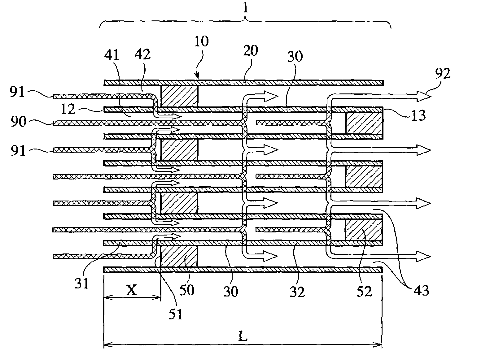
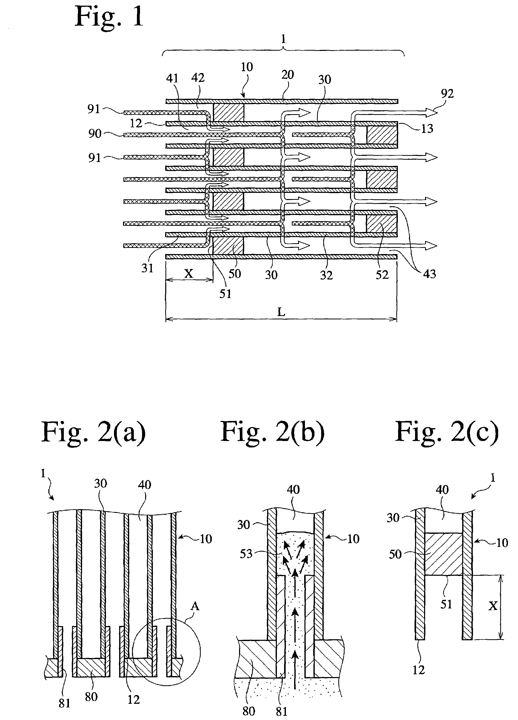
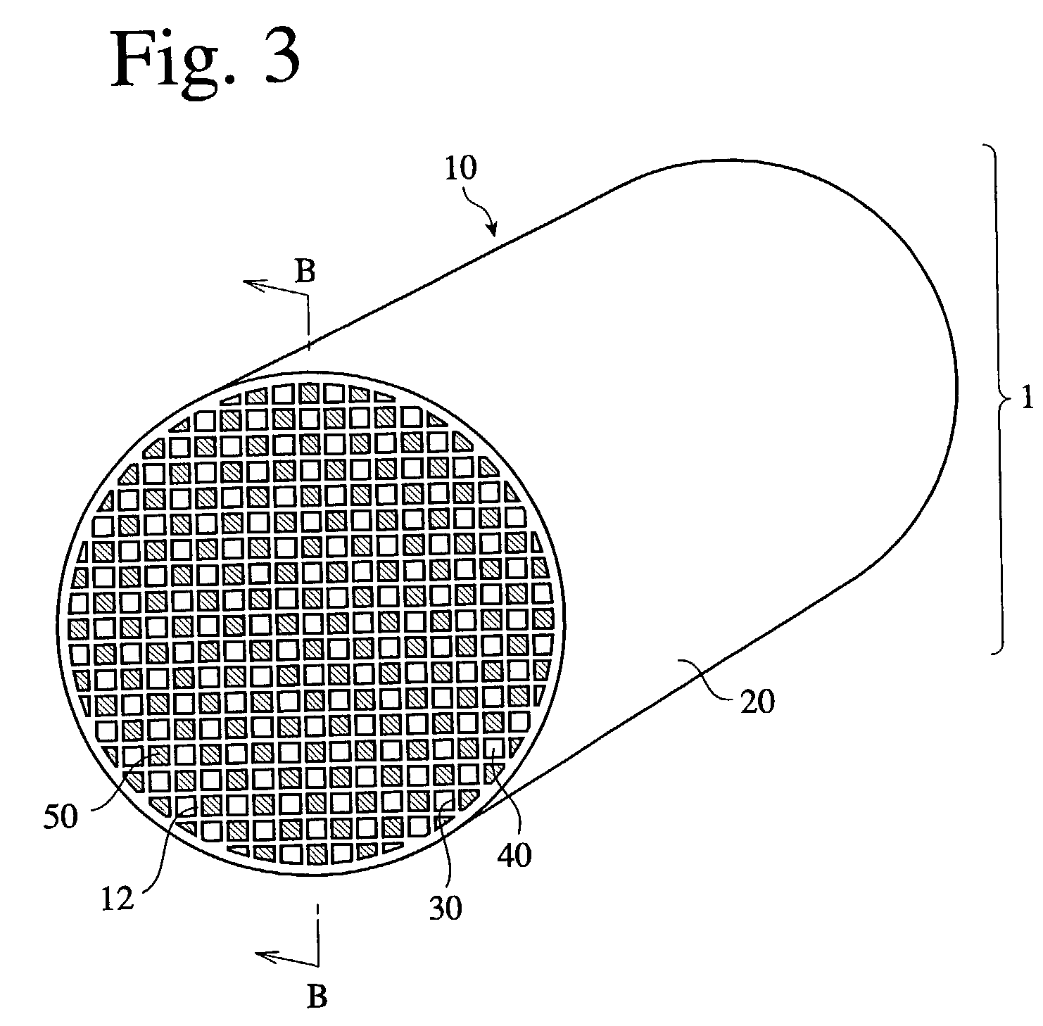
[0064]The paste was extrusion-molded to a green body having a honeycomb structure comprising an outer wall 20, and partition walls 30 defining a plurality of flow paths 40 each having a square cross section. After drying, the green body was calcined to form a porous honeycomb structure 10 having a diameter of 267 mm and an entire length L of 300 mm, the partition walls 30 having a pitc...

example 2

[0074]Honeycomb filters 1 having the structure shown in FIG. 1 (Samples 7 and 8) were produced in the same manner as in Example 1. Each honeycomb filter 1 had a diameter of 267 mm and a length of 300 mm, and its partition walls 30 had a pitch of 1.5 mm, a thickness of 0.3 mm and a porosity of 65%. The distance X from the inlet-side opening end 12 of the honeycomb filter 1 to the front end surface 51 of the plug 50 was 49.8 mm (Sample 7) and 96.3 mm (Sample 8), respectively.

[0075]In each Sample 7, 8, the surfaces and pores of the plugs 50 and the downstream partition wall portions 32 carried a catalyst comprising Pt, cerium oxide and activated alumina. The amount of Pt in the catalyst carried was 1 g / L. A catalyst (Pt: 4 g / L) having a higher Pt concentration than the above catalyst was carried on the surfaces and pores of the partition wall portions 31 upstream of the plugs 50.

[0076]The durability test of each of the resultant ceramic honeycomb filters 1 was carried out in the same m...

example 3

[0079]Honeycomb filters 1 of Samples 9 and 10 each having the structure shown in FIG. 1 were produced in the same manner as in Example 1. Each honeycomb filter 1 had a diameter of 267 mm and a length of 300 mm, and its partition walls 30 had a pitch of 1.5 mm, a thickness of 0.3 mm and a porosity of 65%. In the honeycomb filter 1, the distance X from the inlet-side opening end 12 to the front end surface 51 of the plug 50 was 49.8 mm (Sample 9) and 96.3 mm (Sample 10).

[0080]In each Sample 9, 10, a catalyst 1 comprising Pt, cerium oxide and activated alumina was carried on the surfaces and pores of the partition wall portions 31 upstream of the plugs 50. Thereafter, a catalyst containing lanthanum, cesium and vanadium was carried on the surfaces and pores of the plugs 50 and the downstream partition wall portions 32. This indicated that the catalyst carried on the partition wall portions 31 upstream of the inlet-side plugs 50 had higher activity than the catalyst carried on the downs...


PUM

PropertyMeasurementUnit
thicknessaaaaaaaaaa
porosityaaaaaaaaaa
temperatureaaaaaaaaaa

Abstract

A ceramic honeycomb filter comprising a ceramic honeycomb structure having porous partition walls defining a plurality of flow paths, and plugs disposed inside the flow paths such that an exhaust gas passes through pores of the porous partition walls, thereby removing particulates from the exhaust gas; a catalyst being carried at least partially on the partition walls and / or the plugs; and at least one of plugs on the side of exhaust gas inlets being disposed at a position separate from the inlet-side opening ends of the flow paths. Particulates are removed from the exhaust gas by injecting unburned fuel and / or hydrocarbon in a gaseous state upstream of the inlet-side plugs to maintain at least part of the inlet-side plugs and their downstream regions at a temperature substantially equal to or higher than the lowest activation temperature of the catalyst.

Description

FIELD OF THE INVENTION[0001]The present invention relates to a ceramic honeycomb filter suitable for an exhaust gas-cleaning apparatus for an automobile engine, particularly for a cleaning apparatus for removing particulates from an exhaust gas from a diesel engine, and an exhaust gas-cleaning method using such a ceramic honeycomb filter.BACKGROUND OF THE INVENTION[0002]Recently, ceramic honeycomb filters comprising ceramic honeycomb structures with a plurality of flow paths sealed alternately at both ends have been finding applications in removing particulates containing carbon as a main component from exhaust gases from diesel engines. As shown in FIGS. 3 and 4, a porous ceramic honeycomb filter 1, which is usually substantially cylindrical or elliptical, comprises (a) a porous ceramic honeycomb structure 10 comprising an outer wall 20, and porous partition walls 30 disposed inside the outer wall 20, with a large number of flow paths 40 encircled by the outer wall 20 and the porou...

Claims


Application Information

Patent Timeline
Patent Type & Authority Patents(United States)
IPC IPC(8): F01N3/00B01D53/94B01J35/04F01N3/022F01N3/28
CPCB01D46/2455B01D46/2459B01D53/944B01D2279/30B01J23/63F01N3/0222F01N3/2828F01N2240/20F01N2330/30Y10S55/30Y02T10/12B01D46/2498B01D46/2482B01J35/19B01J35/56
Inventor SUWABE, HIROHISATAKAKURA, TAKASHIMAKITA, SATOSHIFUNABASHI, HIROSHI
Owner HITACHI METALS LTD
Features
  • Generate Ideas
  • Intellectual Property
  • Life Sciences
  • Materials
  • Tech Scout
  • Unparalleled Data Quality
  • Higher Quality Content
  • 60% Fewer Hallucinations
Learn More