Supercharge Your Innovation With Domain-Expert AI Agents!

Stitched write head with staircase P2 defined throat height

a writing head and staircase technology, applied in the direction of magnetic recording heads, magnetic recording instruments, magnetic recording, etc., can solve the problems of narrow write efficiency, narrow write gap and track width, and difficulty in fabricating a precise track width during the photo/trim patterning process, and achieve narrow well-defined track width

Inactive Publication Date: 2006-10-31
HITACHI GLOBAL STORAGE TECH NETHERLANDS BV
View PDF8 Cites 12 Cited by
  • Summary
  • Abstract
  • Description
  • Claims
  • Application Information

AI Technical Summary

Benefits of technology

This approach allows for precise control of throat height and narrow track width, enhancing bit and track density, thereby improving the performance and yield of magnetic disk drives by optimizing flux transfer and reducing fabrication complexities.

Problems solved by technology

In order to achieve required magnetic performance, however, the throat height of the pedestal must be long (1.0 μm–2 μm) so that the P1 pedestal is not over-saturated causing a low write efficiency for a writer with narrow write gap and track width.
Unfortunately, the resist bump creates a non-planar structure near the ABS which makes it difficult to fabricate a precise track width during the photo / trim patterning process.

Method used


Image

  • Stitched write head with staircase P2 defined throat height
  • Stitched write head with staircase P2 defined throat height
  • Stitched write head with staircase P2 defined throat height

Examples


first embodiment

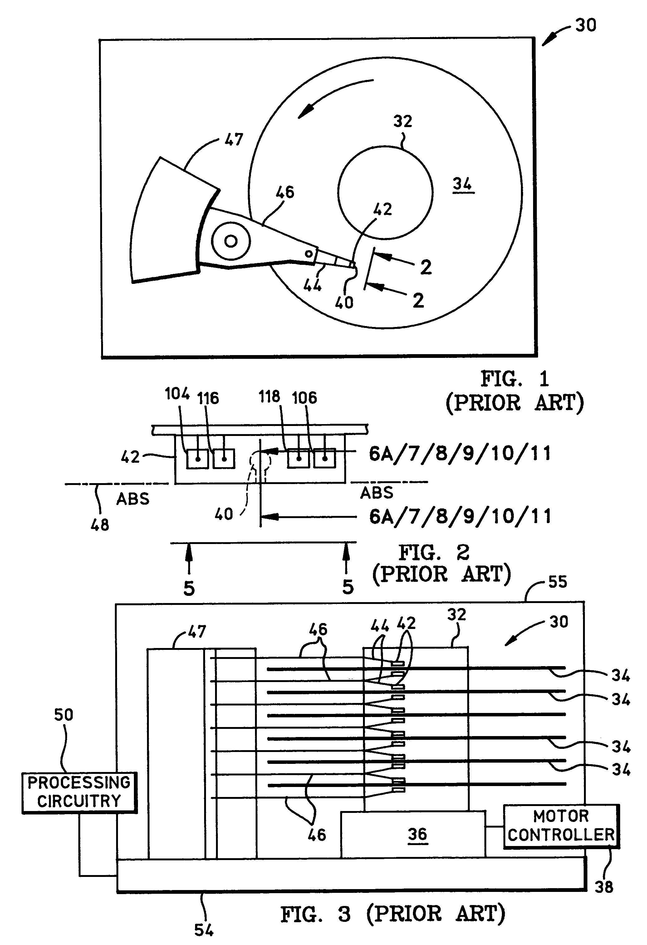
[0028]FIG. 6A is a side cross-sectional elevation view of a magnetic head assembly 200, which includes a write head portion and a read head portion and is the magnetic head assembly 40 in FIG. 2. In the read head a sensor 202 is sandwiched between nonmagnetic electrically insulative first and second read gap layers 204 and 206, and the read gap layers are sandwiched between ferromagnetic first and second shield layers 208 and 210. In response to external magnetic fields, the resistance of the sensor 202 changes. A sense current Is (not shown) conducted through the sensor causes these resistance changes to be manifested as potential changes. These potential changes are then processed as readback signals by the processing circuitry 50 shown in FIG. 3.

[0029]The write head portion includes first and second pole pieces wherein the first pole piece may also include the second shield layer 210 and a first pole piece pedestal 212. When the layer 210 serves as both a second shield layer for ...

embodiment 200

[0033]Another embodiment 300 of the magnetic head assembly is illustrated in FIG. 7 which is the same as the embodiment 200 in FIG. 6A except the second insulation stack 244 with the write coil in FIG. 6A has been eliminated and a third component 302 of the second pole piece is a flat layer instead of an arched layer 230 as shown in FIG. 6A.

[0034]FIG. 8 illustrates a third embodiment 400 of the magnetic head assembly which differs from the embodiment 200 in FIG. 6A in that there is no third component of the second pole piece, the insulation stack 244 with the write coil therein is omitted and the second component 402 of the second pole piece is fabricated somewhat differently. The second component 402 is fabricated with a track width portion 404 which flares out at 236 to form a widened portion 406. The track width portion 404 is employed as a mask for ion milling the first component 226 with the desired track width or may be further ion milled to define the same track width in the ...

fourth embodiment

[0035]FIG. 9 illustrates the magnetic head assembly which differs from the embodiment shown in FIG. 6A in that the pedestal 502 is not milled to form a cap. Instead a first pole piece cap 504 is formed on the pedestal 502, a write gap layer 506 is formed on the cap 504 and the first component 508 of the second pole piece is formed on the write gap 506 with these layers being flush at 232 to define the throat height. The second component 228 of the second pole piece along with other writer layers are constructed similarly as the embodiment shown in FIG. 6A–6C.


PUM

PropertyMeasurementUnit
widthaaaaaaaaaa
heightaaaaaaaaaa
thicknessaaaaaaaaaa

Abstract

A magnetic write head assembly has a head surface and a track width at the head surface wherein the head surface forms a first vertical plane and wherein the head assembly includes first and second pole pieces, a write gap located between the first and second pole pieces, the second pole piece having first and second components wherein the first component is located between the write gap and the second component and each of the first and second components has a height into the head which extends from and which is oriented perpendicular to said head surface, the first component having a uniform thickness throughout its height into the head with the height into the head forming a zero throat (ZTH) which lies in a second vertical plane that is parallel to said first vertical plane, the height into the head of the second component being greater than the height into the head of the first component, and each of the first and second components having said track width at the head surface.

Description

BACKGROUND OF THE INVENTION[0001]1. Field of the Invention[0002]The present invention relates to a stitched write head with a staircase defined second pole piece (P2) throat height and, more particularly, to such a write head and method of making wherein a first component of P2 can be fabricated on a planar surface for defining the throat height and a second component of P2 can be fabricated on a planar surface including the first component with a track width so that the second component can be employed as a mask for ion milling the first component with the track width.[0003]2. Description of the Related Art[0004]The heart of a computer is a magnetic disk drive which includes a rotating magnetic disk, a slider that has a magnetic head assembly which includes write and read heads, a suspension arm. When the disk is not rotating the actuator arm parks the suspension arm on a ramp. When the disk rotates and the slider is positioned by the arm above the disk air is swirled by the rotati...

Claims


Application Information

Patent Timeline
Patent Type & Authority Patents(United States)
IPC IPC(8): G11B5/147G11B5/31
CPCG11B5/3116Y10T29/49032
Inventor SHEN, YONGZHANG, SUE S.
Owner HITACHI GLOBAL STORAGE TECH NETHERLANDS BV
Features
  • R&D
  • Intellectual Property
  • Life Sciences
  • Materials
  • Tech Scout
  • Unparalleled Data Quality
  • Higher Quality Content
  • 60% Fewer Hallucinations
Learn More