Check patentability & draft patents in minutes with Patsnap Eureka AI!

Light release ring for vehicle lights

a technology of vehicle lights and light release rings, which is applied in the field of vehicle lights, can solve the problems of insufficient illumination from optical fibers and high cost of optical fibers

Inactive Publication Date: 2006-12-05
MAXZONE VEHICLE LIGHTING CORP
View PDF3 Cites 15 Cited by
  • Summary
  • Abstract
  • Description
  • Claims
  • Application Information

AI Technical Summary

Benefits of technology

The design enhances the visibility and brightness of the light release ring by directing sub-lamp light beams onto its reflection surface, providing clear illumination even when the main lamp is on, without the need for expensive optical fibers.

Problems solved by technology

However, the optical fibers are expensive and the illumination from the optical fibers is not satisfactorily bright enough.

Method used


Image

  • Light release ring for vehicle lights
  • Light release ring for vehicle lights
  • Light release ring for vehicle lights

Examples


Embodiment Construction

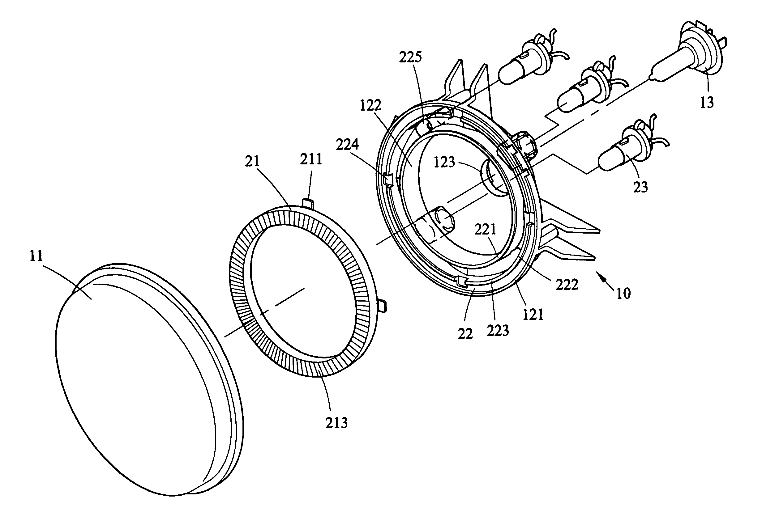
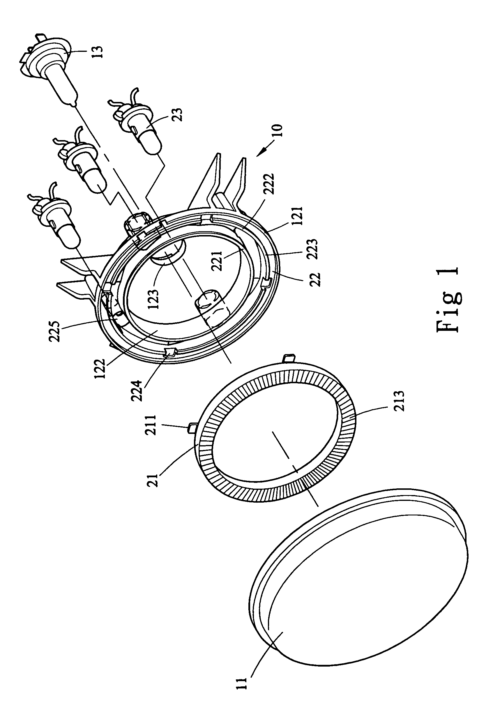
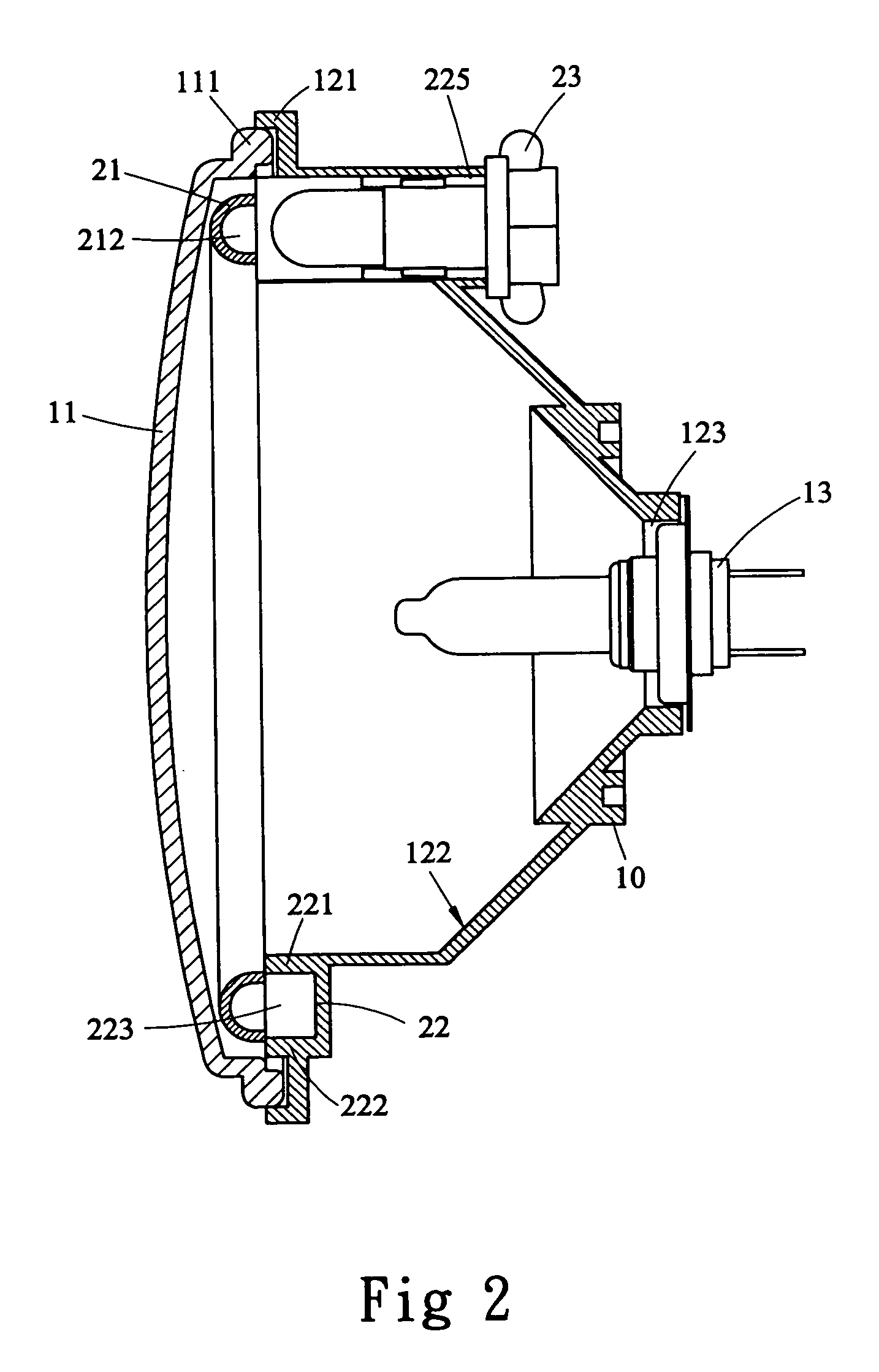
[0016]Referring to FIGS. 1 to 3 and 5, the vehicle light of the present invention comprises a reflector 10 with a concave reflection surface 122 and a main lamp 13 is installed in the hole 123 defined in a center of the concave reflection surface 122. A reflection member 22 is connected to the reflector 10 and includes an inner reflection surface 221 and an outer reflection surface 222 as shown, and an annular groove 223 is defined between the inner and outer reflection surfaces 221, 222. A plurality of sub-lamps 23 are installed in the holes 225 defined in the reflection member 22. A light release ring 21 includes a reflection outer surface 213 and four lugs 211 which extend from an outer periphery thereof and are engaged with holes 224 defined in the reflection member 22. The light release ring 21 is positioned to be engaged with the annular groove 223 and has a reflection inner surface 212. The reflection inner surface 212 of the light release ring 21 is located to face the sub-l...


PUM


Abstract

A vehicle light includes a reflector with a concave reflection surface and a main lamp is connected to a center of the concave reflection surface. A reflection member is connected to the reflector and includes an annular groove with which a light release ring is engaged. A plurality of sub-lamps are connected to the reflection member and light beams emitted by the sub-lamps are toward directly to a reflection inner surface of the light release ring. A cover plate is engaged with the reflection member and encloses the light release ring.

Description

FIELD OF THE INVENTION[0001]The present invention relates to a vehicle light having a light release ring and sub-lamps emit light beam to the light release ring to provide a visible light ring independent from the main lamp.BACKGROUND OF THE INVENTION[0002]A conventional light for vehicles generally includes a main lamp which is located at a focus position of the reflector so as to provide a light beam for illuminating the road in front of the drivers, and a sub-lamp which provide visible light when the main lamp is not in use. U.S. Pat. No. 6,107,916 discloses a signal lamp for vehicles and includes a light release ring made of optical fibers and the sub-lamp emits light toward the optical fibers which indirectly reflect the light beam. However, the optical fibers are expensive and the illumination from the optical fibers is not satisfactorily bright enough. Some lights for vehicles reflect the light beam via the reflector so that the light release ring can be seen. The sub-lamps u...

Claims


Application Information

Patent Timeline
Patent Type & Authority Patents(United States)
IPC IPC(8): B60Q3/04
CPCB60Q1/0052
Inventor HSU, SHU-SHENG
Owner MAXZONE VEHICLE LIGHTING CORP
Features
  • R&D
  • Intellectual Property
  • Life Sciences
  • Materials
  • Tech Scout
  • Unparalleled Data Quality
  • Higher Quality Content
  • 60% Fewer Hallucinations
Learn More