Check patentability & draft patents in minutes with Patsnap Eureka AI!

Apparatus and method of registration correction for video signal processor and a television camera having registration correcting function

a technology of video signal processor and registration correction method, which is applied in the direction of television system, pulse technique, instruments, etc., can solve the problems of deterioration of resolution, inability to adjust the position of elements to eliminate displacement, and inability to register discrepancy, so as to achieve high accuracy the effect of registration correction

Inactive Publication Date: 2007-01-09
KOKUSA ELECTRIC CO LTD
View PDF7 Cites 1 Cited by
  • Summary
  • Abstract
  • Description
  • Claims
  • Application Information

AI Technical Summary

Benefits of technology

The present invention provides an apparatus and method for registration correction in a video signal processor. The apparatus includes interpolation circuits that receive digital sampled pixel signals from multiple color channels and generate a digital pixel signal in a desired position between adjacent signals. The desired position is determined based on a registration discrepancy among the color channels. The apparatus can easily and accurately correct horizontal registration discrepancies caused by position errors of solid state image pickup elements and delay time differences among signal paths. The apparatus also includes variable delay circuits and interpolation circuits for both rough and fine adjustments of registration correction, ensuring high-accuracy registration correction. The technical effects of the invention include improved accuracy and ease of use for video signal processors and television cameras.

Problems solved by technology

In this case, however, when optical alignment of the three solid state image pickup elements is carried out inaccurately, the positions of the elements cannot be re-adjusted to eliminate the displacement.
This results in so-called registration discrepancy in which images based on three color signals are not perfectly matched to one another when they are reproduced.
The registration discrepancy leads to the deterioration of the resolution, the generation of false color signals, and so on.
Thus, the image quality of a reproduced image is deteriorated on a large scale.
Therefore, the required accuracy of positioning is extremely high so that advanced technology and extensive time are required for the positioning work.
In addition, since even slight deformation gives a great influence, it is extremely difficult to keep the performance after manufacturing.
As for horizontal positioning of image pickup elements, delay properties differing among the R, G and B color channels in a video signal circuit system or a signal transmission system such as signal lines also cause a registration discrepancy.
Thus, it is more and more difficult to obtain high precision.
Thus, there are problems that the cost increases and the performance cannot be kept.
That is, since it is necessary to add the analog delay lines, extra wiring and extra work are required so as to cause a lot of labor and time.
Thus, the cost increases.
In addition, since the delay properties using the analog delay lines are fixed, a variety of discrepancies cannot be dealt with flexibly, and a variety of properties cannot be dealt with, either.
Thus, there also arises a problem that the performance cannot be kept.
According to this method, since a plurality of horizontal transfer pulses having different frequencies are produced, the circuit configuration as a whole becomes complicated, and the adjustment is also troublesome.
The correction of chromatic aberration using the two-dimensional filter increases the circuit scale so that the cost increases.

Method used


Image

  • Apparatus and method of registration correction for video signal processor and a television camera having registration correcting function
  • Apparatus and method of registration correction for video signal processor and a television camera having registration correcting function
  • Apparatus and method of registration correction for video signal processor and a television camera having registration correcting function

Examples


Embodiment Construction

[0026]A registration correction apparatus for a television camera according to the present invention will be described below in detail along its embodiments shown in the drawings.

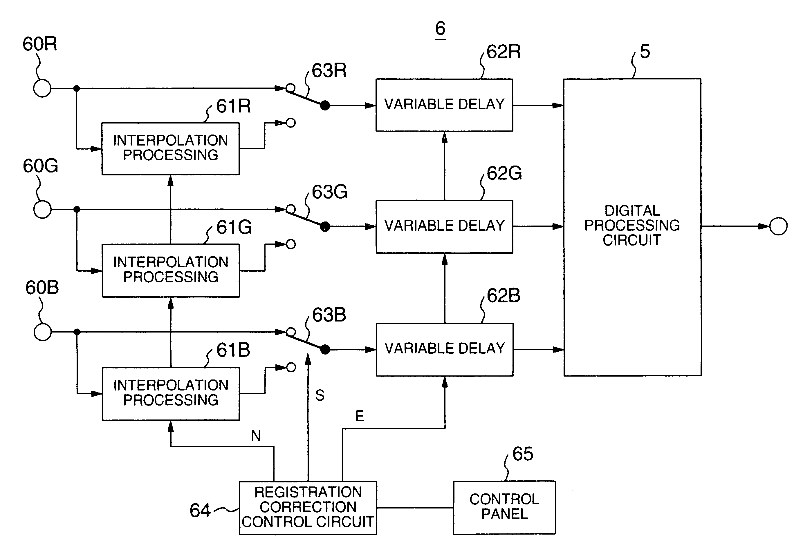
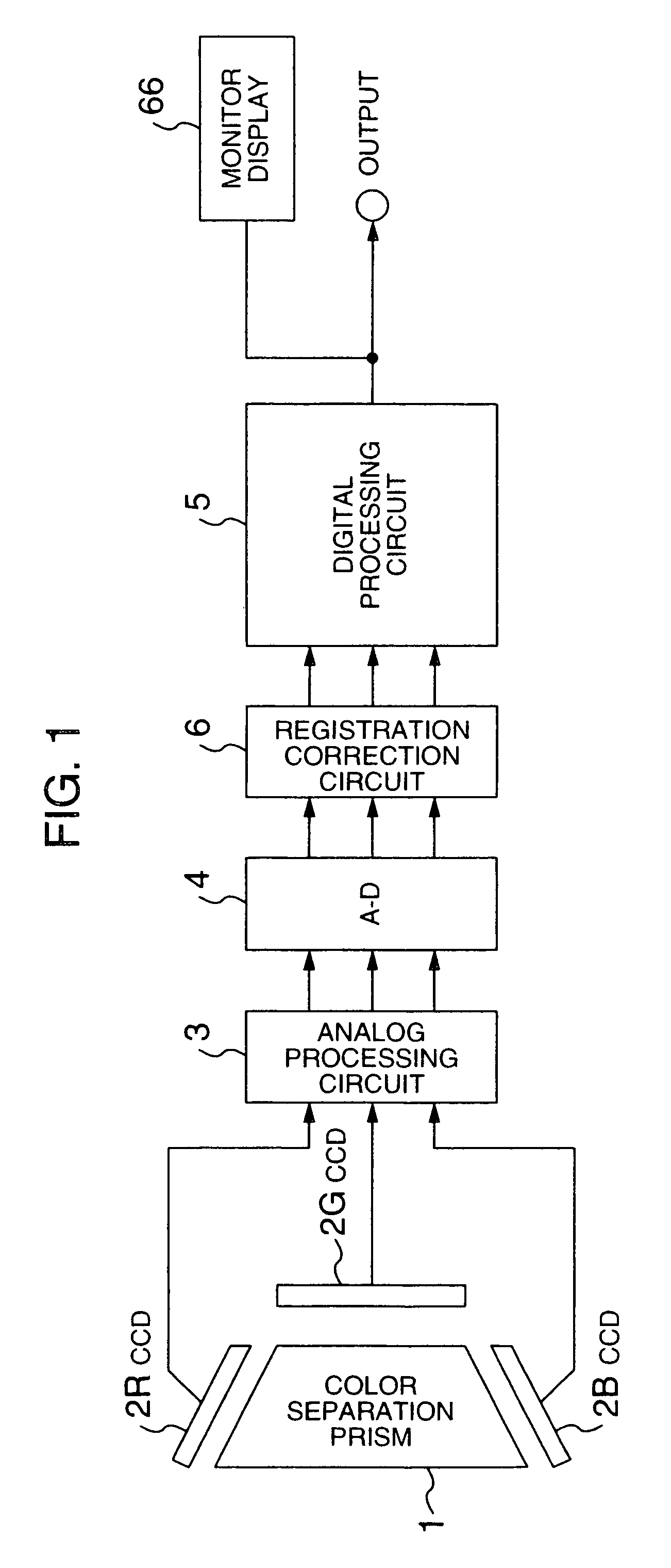
[0027]FIG. 1 shows an embodiment of the present invention. In FIG. 1, the reference numeral 6 represents a registration correction circuit, and the other parts are arranged in the same manner as those in the prior art described with reference to FIG. 7. That is, the registration correction apparatus has a color separation prism 1, solid state image pickup elements 2R, 2G and 2B for respective color channels, an analog signal processing circuit 3, an A / D conversion circuit 4, and a digital signal processing circuit 5, and the registration correction apparatus is designed so that an image signal based on an image of a subject to be picked up can be obtained as an output signal from the digital signal processing circuit 5.

[0028]Here, the registration correction circuit 6 is peculiar to this embodiment. This em...


PUM


Abstract

A registration correction apparatus having interpolation circuits. The interpolation circuits receives digital sampled pixel signals from at least one channel of a plurality of color signal channels. The digital sampled pixel signals have been obtained by sampling consecutive pixel signals. Each of the interpolation circuits generates a digital pixel signal in a desired position between adjacent two of the digital sampled pixel signals by interpolation processing. The desired position between the two adjacent digital sampled pixel signals is set in accordance with a registration discrepancy among the plurality of color signal channels by a control circuit.

Description

BACKGROUND OF THE INVENTION[0001]The present invention relates to a signal processing technique for a video signal processor including a color television camera, and particularly relates to an apparatus and a method of registration discrepancy correction suitable to a television camera used in a system in which image pickup elements are joined to a color separation optical system, and a television camera having a registration correcting function.[0002]So-called three-chip color television cameras are hitherto prevailed as television cameras used for applications such as broadcasting applications in which comparatively high performance specifications are required. The three-chip color television cameras adopt a system in which an incident image is separated into images of the three primary colors R (Red), G (Green) and B (Blue) by a prism, and the color images are transformed into electric signals by solid state image pickup elements such as CCDs respectively.[0003]Here, FIG. 7 shows...

Claims


Application Information

Patent Timeline
Patent Type & Authority Patents(United States)
IPC IPC(8): H04N9/093H04N3/26H04N23/15
CPCH04N9/093H04N23/15
Inventor MURATA, NOBUO
Owner KOKUSA ELECTRIC CO LTD
Features
  • R&D
  • Intellectual Property
  • Life Sciences
  • Materials
  • Tech Scout
  • Unparalleled Data Quality
  • Higher Quality Content
  • 60% Fewer Hallucinations
Learn More