RFID tags with modifiable operating parameters

a technology of operating parameters and radiofrequency identification, which is applied in the direction of burglar alarm mechanical actuation, burglar alarm by hand-portable object removal, instruments, etc., and can solve problems such as reducing the read range of the circui

Active Publication Date: 2007-01-30
AVERY DENNISON CORP
View PDF11 Cites 103 Cited by
  • Summary
  • Abstract
  • Description
  • Claims
  • Application Information

AI Technical Summary

Benefits of technology

[0006]In accordance with exemplary embodiments of the present invention, simple and inexpensive RFID apparatus and methodology are provided that enable RFID tags to operate with multiple read ranges and / or that enable the operating parameters of such tags to be selectively modified.
[0008]In one of the many possible embodiments thereof, the RFID tag may be configured so that the operating parameter that is modified is a read range. For example, the RFID circuit may include an RFID chip and an antenna, and the liner may include an electrical element that modifies a read range of the RFID circuit when the liner is attached to the facestock. More specifically, the electrical element electrically couples with the antenna when the liner is attached to the facestock, thereby reducing the read range of the circuit. When the liner is removed, the electrical element is decoupled from the antenna, thereby enabling the antenna to operate at another read range, i.e., a specified operating range. For example, a coupled read range may be less than about 1 meter, and a decoupled read range may be at least about 2 meters.
[0010]Alternatively, the liner may modify the coupling characteristics of the antenna to a specific coupling structure in an RFID-enabled printer or label applicator. Examples of the coupling characteristics that may be modified include coupling strength, signal level, and coupling frequency. For example, the signal level at which the RFID tag receives the RF signal from a reader may be controlled. In addition, the frequency at which the tag couples efficiently to the reader coupling structure may also be controlled. The control or modification of these characteristics enables tags designed to operate in free space at one frequency band, for example the band from 902 MHz to 928 MHz under FCC part 15 in the United States, to be read and programmed in a printer operating at a frequency allowed in Europe, for example, in the band from 869.4 MHz to 869.650 MHz under ETS 300-220, thereby facilitating international shipping of tagged objects.

Problems solved by technology

More specifically, the electrical element electrically couples with the antenna when the liner is attached to the facestock, thereby reducing the read range of the circuit.

Method used


Image

  • RFID tags with modifiable operating parameters
  • RFID tags with modifiable operating parameters
  • RFID tags with modifiable operating parameters

Examples


Embodiment Construction

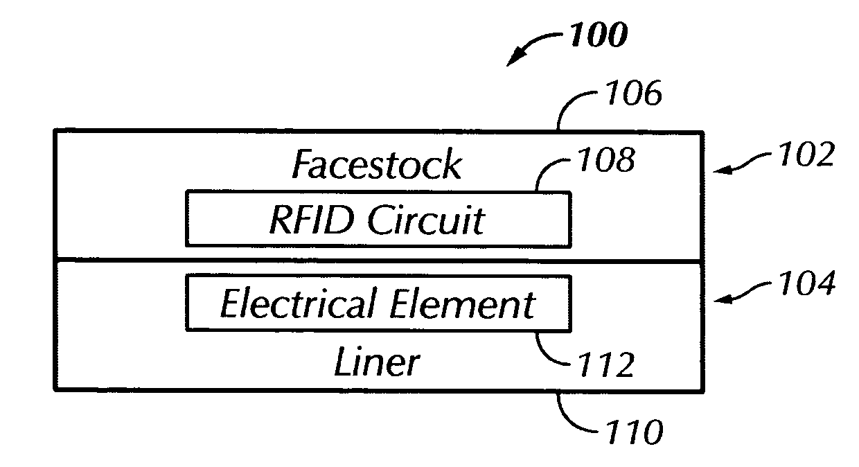
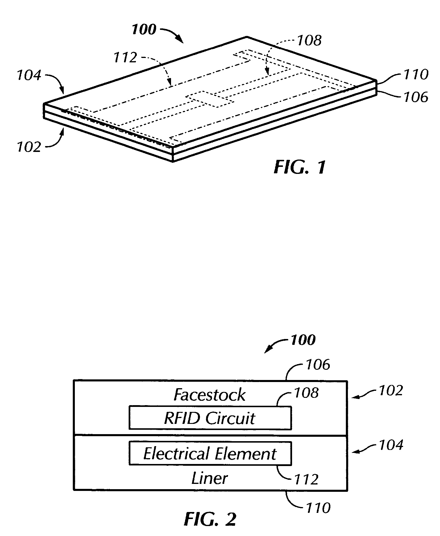
[0037]Referring more particularly to FIG. 1 of the drawings, a radio-frequency identification (RFID) tag 100 is configured so that the tag has more than one read characteristic. For example, in a number of embodiments, the tag 100 may have both short-range read characteristics and long-range read characteristics. For the purposes of this description, an RFID tag with such multiple read-range characteristics may be described as a two-state, a dual-state, or a multi-state tag.

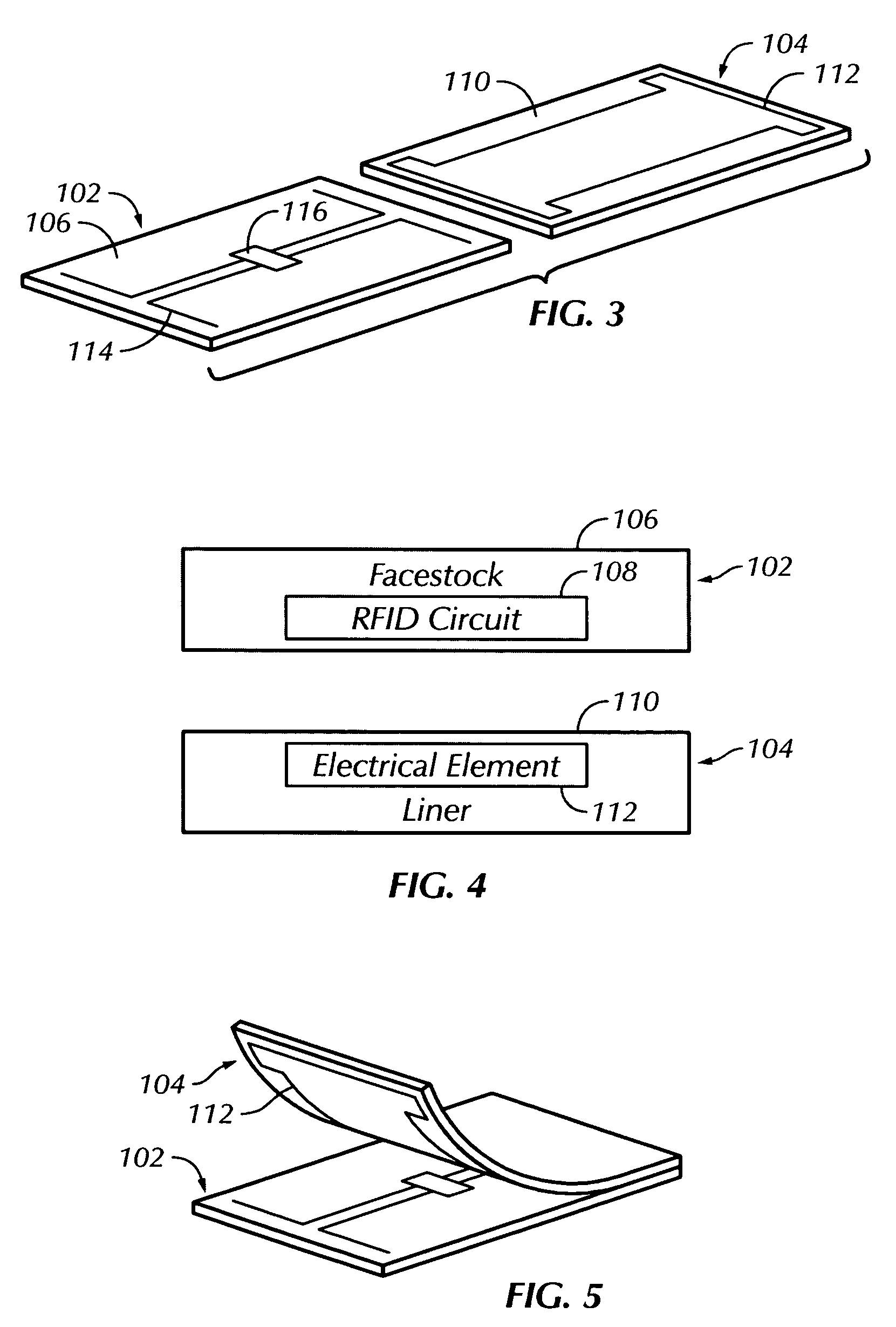
[0038]Referring to the embodiments shown in FIGS. 1 and 2, a tag 100 may include a facestock 102 and a liner104 releasably attached to the facestock 102. The facestock 102 may include a substrate 106 and an RFID circuit 108. The liner 104 may include a substrate 110 and an electrical element 112 for interacting with the RFID circuit 108 so as to modify an electrical characteristic or an operating parameter of the RFID tag 100.

[0039]The RFID circuit 108 can comprise an inlay 104 of a known type, i.e., a chip 116, ...


PUM

PropertyMeasurementUnit
frequencyaaaaaaaaaa
frequencyaaaaaaaaaa
frequencyaaaaaaaaaa

Abstract

A radio-frequency identification (RFID) tag includes a facestock and a liner. The facestock includes an RFID circuit with an operating parameter, and the liner is releasably attached to the facestock such that when the liner is detached from the facestock, the operating parameter of the RFID circuit is desirably modified. The RFID tag may be configured so that the operating parameter that is modified is, for example, a read range or a propagation direction. The RFID circuit may include an RFID chip and an antenna, and the liner may include an electrical element that modifies a read range of the RFID circuit when the liner is attached to the facestock. More specifically, the electrical element may electrically couple with the antenna when the liner is attached to the facestock, thereby reducing the read range of the circuit. When the liner is removed, the antenna is decoupled from the electrical element and thereby enabled to operate at another read range, i.e., a specified operating range. Alternatively, the electrical element may couple with the antenna of the RFID circuit so that energy is propagated from the element in a direction that is orthogonal to a normal direction of propagation of the antenna.

Description

BACKGROUND OF THE INVENTION[0001]The present invention relates to radio-frequency identification (RFID) tags. The invention also relates to RFID apparatus and methodology that enable the RFID tags to operate with multiple read ranges and / or that enable tags to have their operating characteristics modified.[0002]Automatic identification is the broad term applying to a host of technologies that are used to help machines identify objects. Automatic identification is often coupled with automatic data capture. Therefore, companies wanting to identify items are able to capture information about the items, to store the captured information in a computer, and to retrieve selectively the information from the computer for a variety of useful purposes, all with minimal human labor.[0003]One type of automatic identification technology is radio-frequency identification (RFID). Radio-frequency identification is a generic term for technologies that use radio waves to automatically identify objects...

Claims


Application Information

Patent Timeline
Patent Type & Authority Patents(United States)
IPC IPC(8): G08B13/14
CPCG06K17/0025G06K19/0724G06K19/0739G06K19/07749G06K19/07718Y10T29/49018G06K2017/009Y10T29/49128G06K19/077G06K19/07
Inventor FORSTER, IAN JAMES
Owner AVERY DENNISON CORP
Why Eureka
Try Eureka