Supercharge Your Innovation With Domain-Expert AI Agents!

Keystone correction derived from the parameters of projectors

a technology of keystone correction and projector, which is applied in the field of projectors, can solve problems such as image distortion, failure to solve the problem completely, and all of these systems suffered from a common problem

Active Publication Date: 2007-02-13
PIXELWORKS SEMICON TECH SHANGHAI CO LTD
View PDF25 Cites 1 Cited by
  • Summary
  • Abstract
  • Description
  • Claims
  • Application Information

AI Technical Summary

Benefits of technology

This method provides a comprehensive solution to correct image distortion by accurately computing and adjusting image corner points based on tilt angles, ensuring a correctly scaled and undistorted image projection even on non-parallel surfaces, addressing the limitations of prior art.

Problems solved by technology

But all of these systems suffered from a common problem.
If the surface onto which the image is projected is not parallel to the front face of the projector, the image is distorted.
But each of these patents fails to completely solve the problem.
U.S. Pat. No. 6,520,547, which uses 3×3 rotation matrices, does not work in a digital environment.
U.S. Pat. No. 6,305,805 warps the image by adding or deleting pixels, which is not an acceptable practice.

Method used


Image

  • Keystone correction derived from the parameters of projectors
  • Keystone correction derived from the parameters of projectors
  • Keystone correction derived from the parameters of projectors

Examples


Embodiment Construction

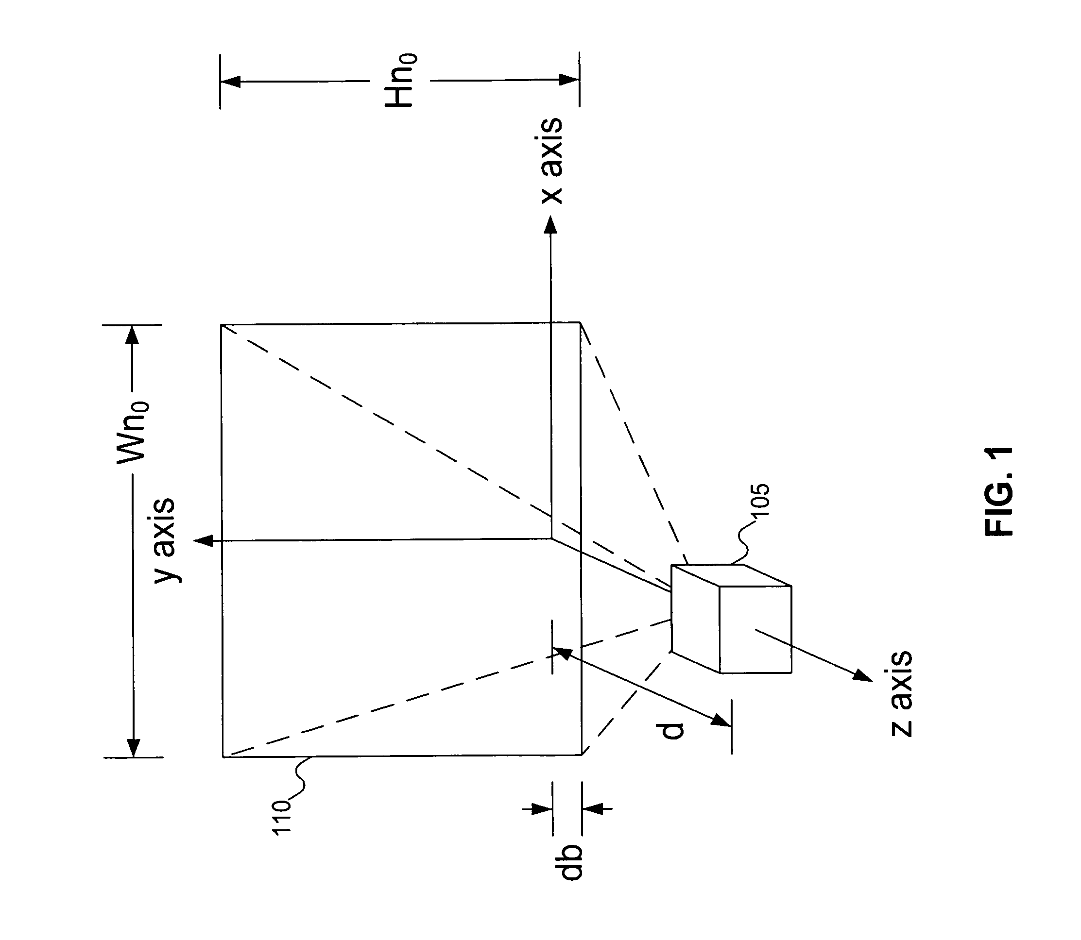
[0014]FIG. 1 shows the inherent parameters of a projector. In FIG. 1, projector 105 is shown projecting image 110. Image 110 is projected onto a surface (not shown). Under ideal circumstances, image 110 is projected onto the projection surface in such a way that, without correction, image 110 is perfectly rectangular. A coordinate system can be superimposed in the space, with the image in the XY-plane and projector 105 along the Z-axis, as shown in FIG. 1. The Z-axis is also called the normal projection line (NPL).

[0015]In a preferred embodiment, the coordinate axes are positioned so that the Y-axis divides image 110 into two equal portions. That is, half of image 110 is to the left of the Y-axis, and half of image 110 is to the right of the Y-axis. But a person skilled in the art will recognize that this is not required, and that the image can be projected in a different spatial position than that shown in FIG. 1 (with image 110 still lying in the XY-plane).

[0016]Projector 105 proj...


PUM


Abstract

A projector determines horizontal and vertical tilt angles. Using the tilt angles and the inherent properties of the projector, keystone correction corner points for the image can be computed. The keystone correction corner points can be used to perform keystone correction on the image.

Description

[0001]This application is a continuation of U.S. patent application Ser. No. 10 / 849,998, filed May 19, 2004, now U.S. Pat. No. 6,997,563, and is incorporated herein by reference for all intents and purposes.FIELD OF THE INVENTION[0002]This invention pertains to projectors, and more particularly to correcting distortion in a projected image.BACKGROUND OF THE INVENTION[0003]Projectors have been around for quite some time. Historically, they projected only static images. The image to be projected would be placed a horizontal surface above a light source. Mirrors would then reflect the image onto a vertical surface parallel to the front of the projector, for easy viewing. The image could be raised or lowered by changing the angle of the mirror, and could be focused by raising or lowering the mirror (thereby changing the focal length of the projector).[0004]With the advent of computers, manufacturers realized that projectors might be able to project dynamic (that is, changing) images. Th...

Claims


Application Information

Patent Timeline
Patent Type & Authority Patents(United States)
IPC IPC(8): G03B21/00G03B21/14
CPCH04N9/3185G03B21/14
Inventor WANG, ZHONGDETENG, TIANBING BRIAN
Owner PIXELWORKS SEMICON TECH SHANGHAI CO LTD
Features
  • R&D
  • Intellectual Property
  • Life Sciences
  • Materials
  • Tech Scout
  • Unparalleled Data Quality
  • Higher Quality Content
  • 60% Fewer Hallucinations
Learn More