Read-out scanning exposure method and apparatus
a technology of exposure method and exposure apparatus, which is applied in the direction of instruments, television systems, conversion screens, etc., can solve the problems of inability to quickly move the line light source, inability to keep the readout speed high, and the thickness so as to achieve the effect of keeping the cost of the readout scanning exposure apparatus low
- Summary
- Abstract
- Description
- Claims
- Application Information
AI Technical Summary
Benefits of technology
Problems solved by technology
Method used
Image

Examples
first embodiment
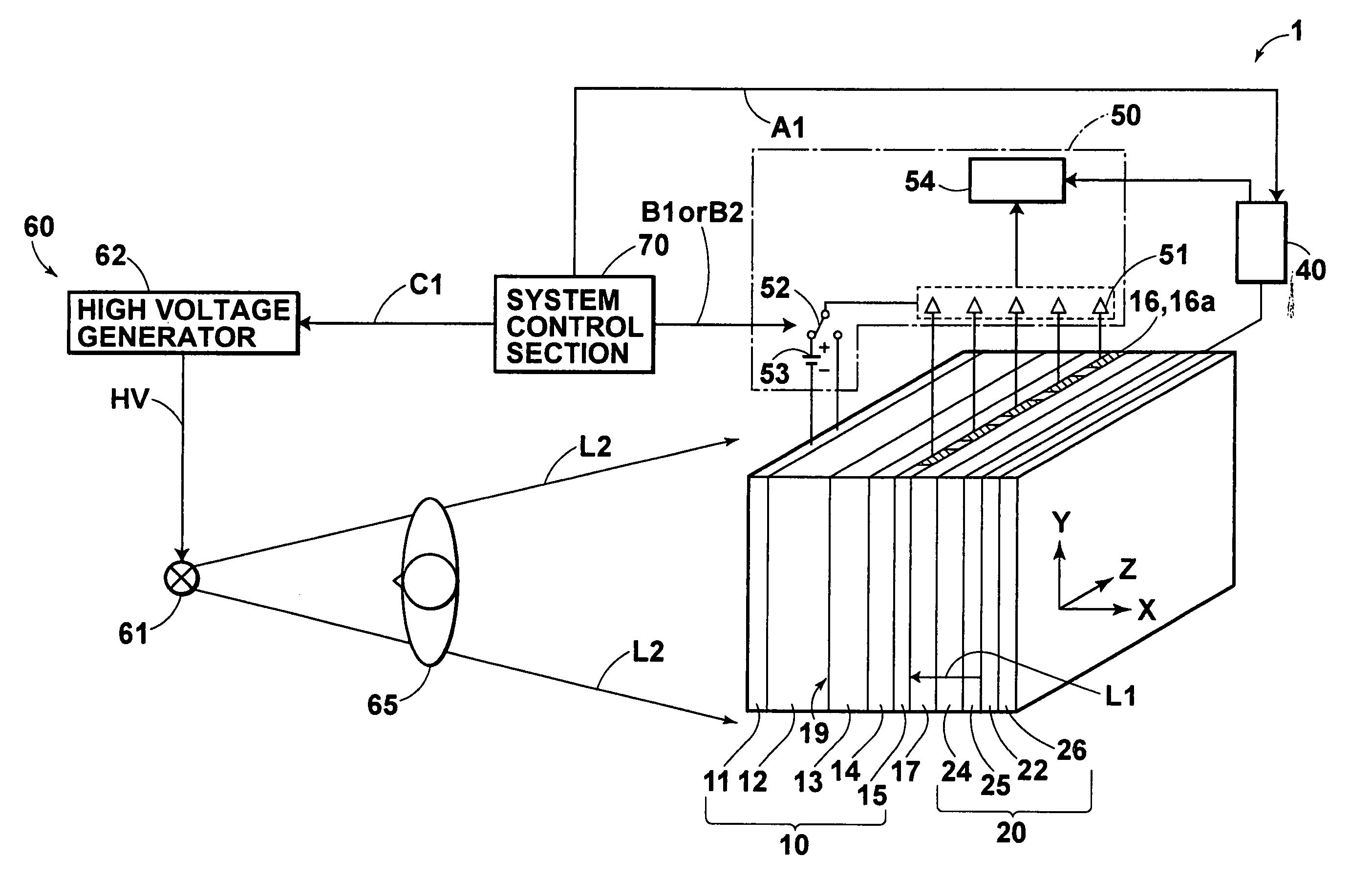
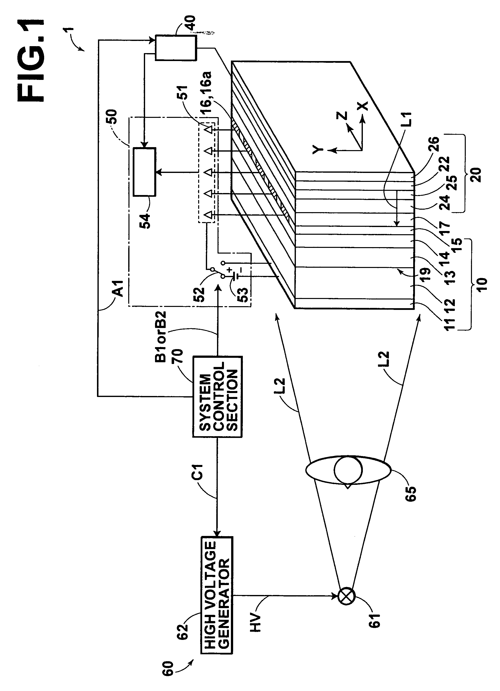
[0074]FIG. 1 is a schematic view showing an image information recording and read-out system, in which the read-out scanning exposure apparatus in accordance with the present invention is employed. As illustrated in FIG. 1, an image information recording and read-out system 1 comprises an image recording medium 10, which is capable of recording an electrostatic latent image having a size of 400 mm×400 mm thereon. The image information recording and read-out system 1 also comprises a scanning exposure section 20, which performs scanning exposure of the image recording medium 10 with reading light beams L1, L1, . . . . The image information recording and read-out system 1 further comprises a scanning exposure control section 40, which controls an operation of the scanning exposure section 20. The image information recording and read-out system 1 still further comprises a reading section 50, which reads image information from the image recording medium 10. The image information recordin...
second embodiment
[0114]As a modification of the read-out scanning exposure apparatus in accordance with the present invention, a slit array plate 88 illustrated in FIG. 8 may be employed. The slit array plate 88 comprises the slit array thin plates 84a, 84b, and 87. As illustrated in FIG. 9, the slit array thin plate 87 has a thickness of 500 μm and is provided with slits 89, 89, . . . , each of which has a width of 150 μm. The slits 89, 89, . . . are located at pitches of 200 μm. The slit array plate 88 having the constitution described above is low in cost and light in weight. Therefore, the scanning exposure section is capable of being kept low in cost and light in weight.
third embodiment
[0115]An image information read-out system, in which the read-out scanning exposure apparatus in accordance with the present invention is employed, will be described hereinbelow with reference to FIG. 10. FIG. 10 shows an image information read-out system 3 for reading out an image from a stimulable phosphor sheet, in which the scanning exposure section 20 for readout is employed.
[0116]With reference to FIG. 10, the image information read-out system 3 comprises the scanning exposure section 20 for irradiating the reading light beams L1, L1, . . . to a stimulable phosphor sheet 90, on which a radiation image has been stored. The image information read-out system 3 also comprises a scanning exposure control section 43. The image information read-out system 3 further comprises a photodetector 91 for detecting light M, which is emitted by the stimulable phosphor sheet 90 when the stimulable phosphor sheet 90 is exposed to the reading light beams L1, L1, . . . . The image information rea...
PUM
| Property | Measurement | Unit |
|---|---|---|
| thickness | aaaaa | aaaaa |
| size | aaaaa | aaaaa |
| thickness | aaaaa | aaaaa |
Abstract
Description
Claims
Application Information
 - R&D
- Intellectual Property
- Life Sciences
- Materials
- Tech Scout
- Unparalleled Data Quality
- Higher Quality Content
- 60% Fewer Hallucinations
Browse by: Latest US Patents, China's latest patents, Technical Efficacy Thesaurus, Application Domain, Technology Topic, Popular Technical Reports.
© 2025 PatSnap. All rights reserved.Legal|Privacy policy|Modern Slavery Act Transparency Statement|Sitemap|About US| Contact US: help@patsnap.com