Check patentability & draft patents in minutes with Patsnap Eureka AI!

Power supply for electronic switch

a technology of electronic switch and power supply, which is applied in the direction of pulse generator, pulse technique, pulse train generator, etc., can solve the problems of significant cumulative power usage, damage to the components of the remote power switch or adjacent electronic circuit, etc., and achieve the effect of not discharging facility power, significant and dramatic improvement of the efficiency of the remote power switch

Inactive Publication Date: 2007-02-27
ME ELECTRONICS PRODS
View PDF2 Cites 14 Cited by
  • Summary
  • Abstract
  • Description
  • Claims
  • Application Information

AI Technical Summary

Benefits of technology

[0007]The inventive remote power switch design employs a transistor to tap a small amount of facility power for use by the control device of the remote power switch. When the transistor is off, it does not dissipate any facility power and, therefore, does not radiate heat. The pulse-generating circuit may be tuned to deliver only the power required by the control device. The efficiency of the remote power switch is dramatically improved according to this aspect of the present invention.
[0009]Magnetically coupling the pulse-generating circuit to the power supply effectively electrically isolates the control device from facility power. This protects the control device from power surges in facility power and prevents transmission of RF noise from the control device onto facility power. It is an object of the present invention to provide a new and improved remote power switch where the control device is electrically isolated from facility power.
[0010]The remote power switch may be mounted in the junction box the wall switch or wall outlet it replaces was mounted and may include a receiver for infrared or RF wireless signals as is known in the art. In such circumstances, a remote control is used to communicate with the remote power switch. An aspect of the present invention relates to color-coding of the remote power switch to match the color of the corresponding actuation key on the remote controller. Such color-coding may assist the operator in selecting the proper remote and actuation key for the desired action.

Problems solved by technology

If each remote power switch continuously taps a small amount of facility power, the cumulative power usage can be significant.
Overheating within the enclosure of the remote power switch may damage the components of the remote power switch or adjacent electronic circuits.

Method used


Image

  • Power supply for electronic switch
  • Power supply for electronic switch
  • Power supply for electronic switch

Examples


Embodiment Construction

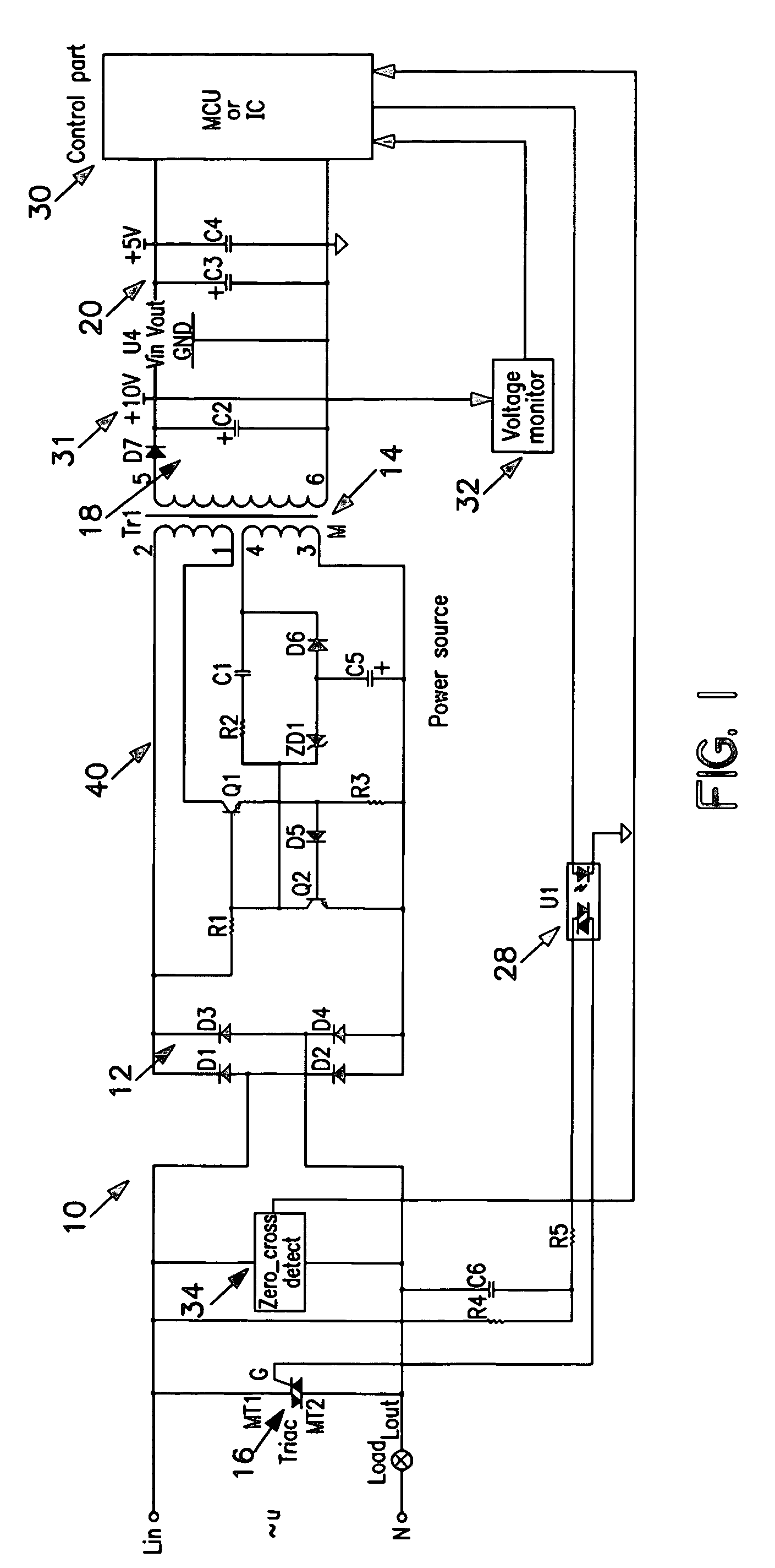
[0018]FIG. 1 is a schematic of a representative remote power switch 10 according to aspects of the present invention. The remote power switch 10 includes an electrically actuated power delivery device 16 responsive to a signal to deliver facility power to a load. The load may be computer or communications equipment such as a server, lighting or some other appliance. The power delivery device 16 is connected to interrupt one leg of the facility power connection to the load. The remote power switch 10 includes a control part 30 that generates the power signal for actuating the power delivery device 16. Particular aspects of the present invention relate to an approach to tapping facility power to supply electrical energy to the control part 30 of the remote power switch 10.

[0019]The remote power switch 10 is configured to replace conventional switches or outlets. A remote power switch will typically be installed in the junction box that housed the switch or outlet being replaced. The j...


PUM


Abstract

A remote power switch uses the initial portion of each AC positive and negative going current pulse to generate power for the controller. This is accomplished by removing the gate signal from an electronic power delivery component at each zero cross and restoring the gate signal after sufficient power has been stored to power the controller for the remainder of each AC current pulse. The majority of each current pulse is delivered through the electronic power delivery component to the load. One embodiment employs a transistor oscillator with transformer feed back to produce a self-regulating power supply. An aspect of the present invention relates to color-coding of a switch cover of the remote power switch to match the color of the corresponding actuation key on the remote controller.

Description

BACKGROUND OF THE INVENTION[0001]1. Field of the Invention[0002]The invention relates generally to power supplies and more particularly to a power supply employing a pulse-generating circuit magnetically coupled to a power supply to provide operating voltage for a remote power switch.[0003]2. Description of the Related Art[0004]Electrically actuated “remote” switches are used to replace mechanical switches in a wide variety of applications. In a recent trend, remote switches are being employed to replace conventional mechanically actuated switches for computer and communications equipment as well as ordinary wall switches in the home. A remote power switch permits service personnel to remotely power down and re-boot computers, servers and the like to remove possible causes of malfunction. Remotely actuated wall switches permit automated control over lighting and home appliances. Further, remotely actuated wall switches allow the user to adjust appliances using a remote control.[0005...

Claims


Application Information

Patent Timeline
Patent Type & Authority Patents(United States)
IPC IPC(8): H01H35/00H02M5/257H03K3/30H03K17/13H03K17/785
CPCH02M5/2573H03K17/136H03K3/30H02M2001/0006H03K17/785H02M1/0006
Inventor TO, WAI HUNG
Owner ME ELECTRONICS PRODS
Features
  • R&D
  • Intellectual Property
  • Life Sciences
  • Materials
  • Tech Scout
  • Unparalleled Data Quality
  • Higher Quality Content
  • 60% Fewer Hallucinations
Learn More