Check patentability & draft patents in minutes with Patsnap Eureka AI!

Turbojet diffuser

a technology of diffuser and diffuser, which is applied in the direction of machines/engines, liquid fuel engines, light and heating apparatus, etc., can solve the problems of diffuser, which has a considerably shorter life, and cannot be separated from the casing, so as to achieve the effect of simple disassembly

Active Publication Date: 2007-04-03
SN DETUDE & DE CONSTR DE MOTEURS DAVIATION S N E C M A
View PDF4 Cites 14 Cited by
  • Summary
  • Abstract
  • Description
  • Claims
  • Application Information

AI Technical Summary

Benefits of technology

Enables easy disassembly and increased diffuser lifetime by distributing stresses and maintaining air intake specifications, while being cost-effective and simple to implement.

Problems solved by technology

The drawback of that prior art is that the diffuser, which has a lifetime that is considerably shorter than that of the combustion chamber casing, is not separable from the casing.
Nevertheless, that is not possible because of constraints associated with taking air from the compressor, whereby an annular space formed around the stator of the compressor extends downstream to the vicinity of the upstream portion of the diffuser and is defined by a transverse wall that is secured to the outer casing of the compressor and that constitutes an obstacle in this location against receiving a diffuser-fastening frustoconical wall or web extending from the diffuser towards the compressor.
That problem might be solved by means of structural arms connected to the outer longitudinal wall of the diffuser downstream from the stator blades, but that would require the diffuser to be made in two parts, which would complicate manufacture and increase its cost.

Method used


Image

  • Turbojet diffuser
  • Turbojet diffuser
  • Turbojet diffuser

Examples


Embodiment Construction

[0020]In the drawings, the left-hand side is upstream or towards the front of the turbojet and the right-hand side is downstream or towards the rear.

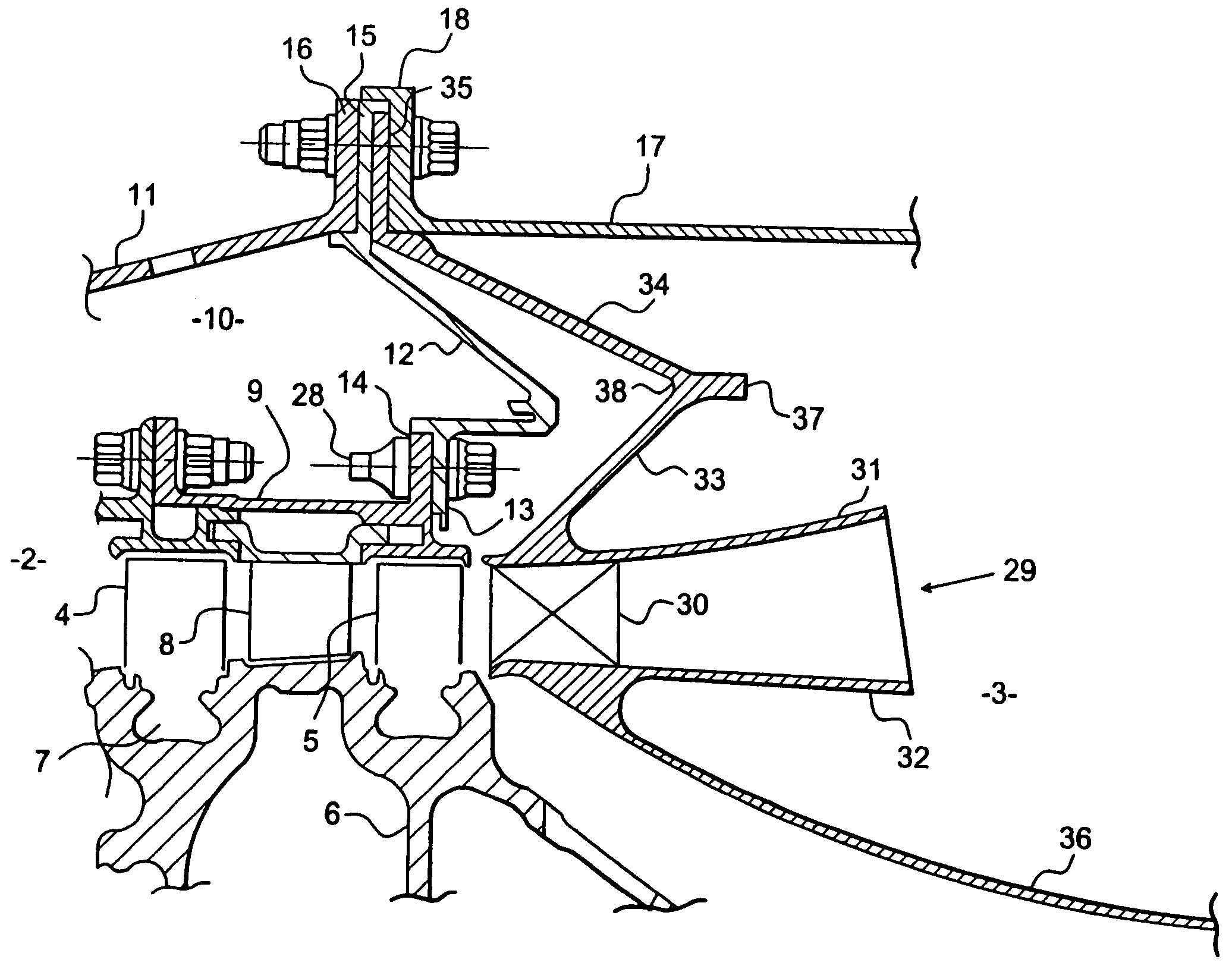
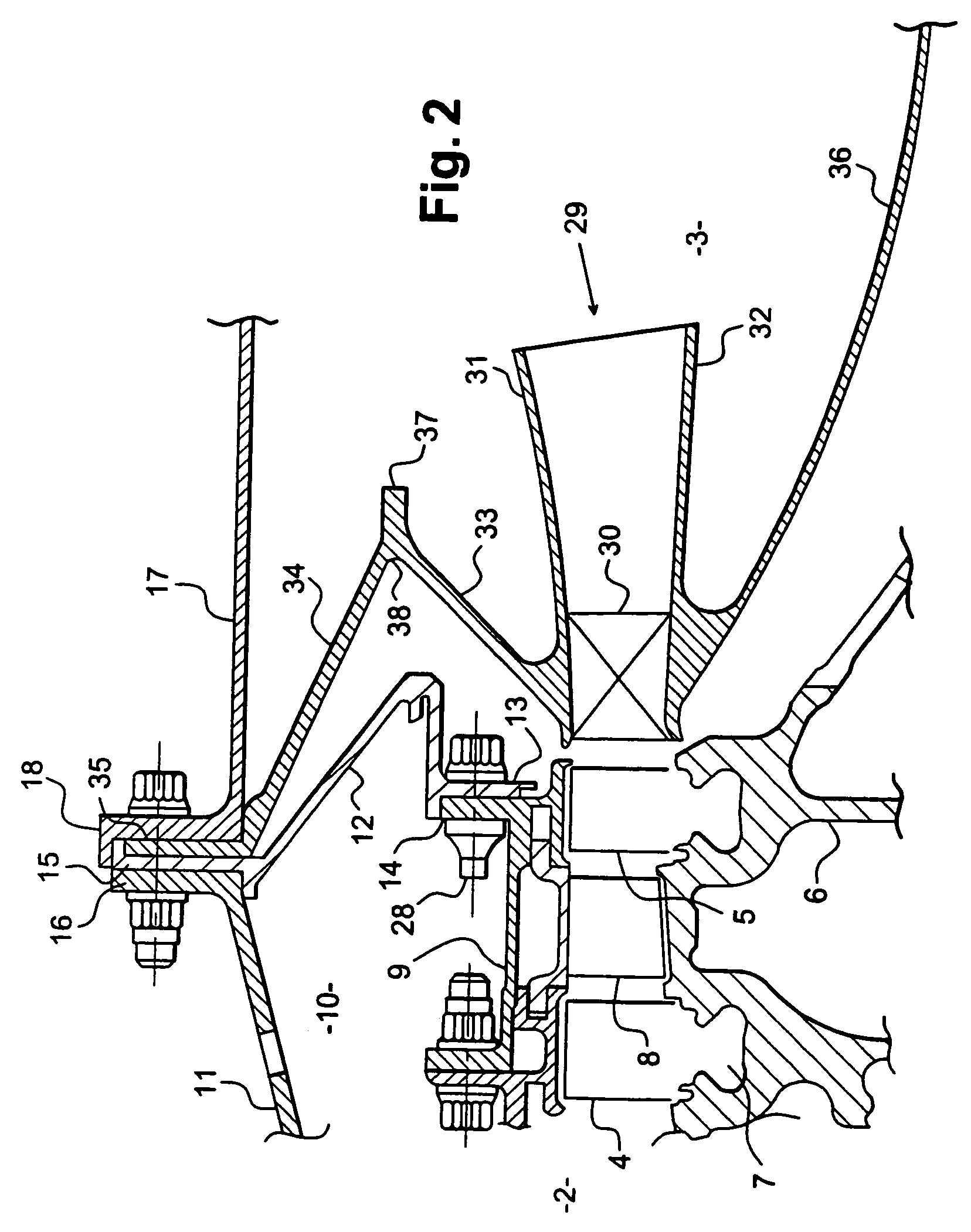
[0021]In FIG. 1, reference 1 designates a prior art diffuser arranged between an upstream compressor 2 and a downstream combustion chamber 3 in a turbojet.

[0022]The compressor 2 is a high pressure compressor and comprises a plurality of stages of moving blades 4, 5 mounted on a rotor 6 of the turbojet by appropriate means 7, e.g. of the dovetail type, and stages of nozzle-forming stationary blades 8 mounted on a stator 9 of the turbojet by appropriate means. In FIG. 1, there are shown only two stages of moving blades 4 and 5 and one stage of stationary blades 8 disposed between the two stages of moving blades 4 and 5.

[0023]An annular space 10 is defined around the stator 9 of the compressor 2 by an outer casing 11 and by a rear transverse wall 12 which is mounted by means of an inner annular flange 13 to an annular flange 14 of the stat...


PUM


Abstract

A turbojet diffuser disposed between a compressor and a combustion chamber, and secured to an outer upstream annular flange of an outer casing of the combustion chamber by suspension means which comprise a first frustoconical wall extending from the outer longitudinal wall of the diffuser towards the combustion chamber, and a second frustoconical wall extending towards the compressor between the first frustoconical wall and the outer casing of the combustion chamber.

Description

[0001]The present invention relates to a turbojet diffuser, the diffuser being disposed between a compressor and a combustion chamber in the turbojet.BACKGROUND OF THE INVENTION[0002]In the prior art, the diffuser is often secured inside an outer casing of the combustion chamber by a thin wall or web of frustoconical shape which extends from an outer longitudinal wall of the diffuser towards the combustion chamber, and which is welded at its radially outer end to the outer casing of the combustion chamber.[0003]The drawback of that prior art is that the diffuser, which has a lifetime that is considerably shorter than that of the combustion chamber casing, is not separable from the casing.[0004]It is therefore desirable to secure the diffuser in removable manner to the outer casing of the combustion chamber. In order to make it easier to remove the diffuser, a better technique would be to secure it by means of an outer annular flange inserted between the annular flanges for coupling ...

Claims


Application Information

Patent Timeline
Patent Type & Authority Patents(United States)
IPC IPC(8): F02C7/00F04D29/54F23R3/60F23R3/04
CPCF04D29/542F23R3/60F05B2230/606
Inventor MARNAS, LAURENTPIEUSSERGUES, CHRISTOPHESABLAYROLLES, PIERRETRAHOT, DENIS
Owner SN DETUDE & DE CONSTR DE MOTEURS DAVIATION S N E C M A
Features
  • R&D
  • Intellectual Property
  • Life Sciences
  • Materials
  • Tech Scout
  • Unparalleled Data Quality
  • Higher Quality Content
  • 60% Fewer Hallucinations
Learn More