Supercharge Your Innovation With Domain-Expert AI Agents!

Heating plate and process for producing the same

a technology of heat transfer and heat transfer plate, which is applied in the field of heat transfer plate, can solve the problems of increasing costs, affecting the production process, and reducing the development time, so as to achieve the effect of reducing costs, facilitating production, and enhancing heat transfer properties

Inactive Publication Date: 2007-04-03
FUJIFILM CORP +1
View PDF3 Cites 3 Cited by
  • Summary
  • Abstract
  • Description
  • Claims
  • Application Information

AI Technical Summary

Benefits of technology

The solution enables cost-effective production of heating plates with enhanced heat transfer and soaking effects, achieving stable and uniform heating of medical imaging materials, reducing production complexity and costs while shortening temperature rise times.

Problems solved by technology

So far, in the heat development device, for the purpose of making the guide surface of a heating section with which the heat development recording material comes into contact uniform, the heat control is carried out while accurately controlling plural heaters, and therefore, this complicated control resulted in an increase in costs.
For this reason, it was difficult to shorten the rise time until the temperature reaches a prescribed development temperature, leading to an obstacle to shortening of the development time.
However, in the foregoing heating plate 1, it is necessary to bore plural communicating holes 3 in parallel to the front surface 2b or the rear surface 2c from the side surface 2a of the metal plate 2, and there was encountered such a problem that the processing is difficult, resulting in an increase in costs.
Further, there is a disadvantage that the processing precision becomes severe for inserting the wick 4 into the communicating hole 3.
Thus, this case also involved such inconveniences that high processing precision is required in boring processing and that the processing is difficult.

Method used


Image

  • Heating plate and process for producing the same
  • Heating plate and process for producing the same
  • Heating plate and process for producing the same

Examples


first embodiment

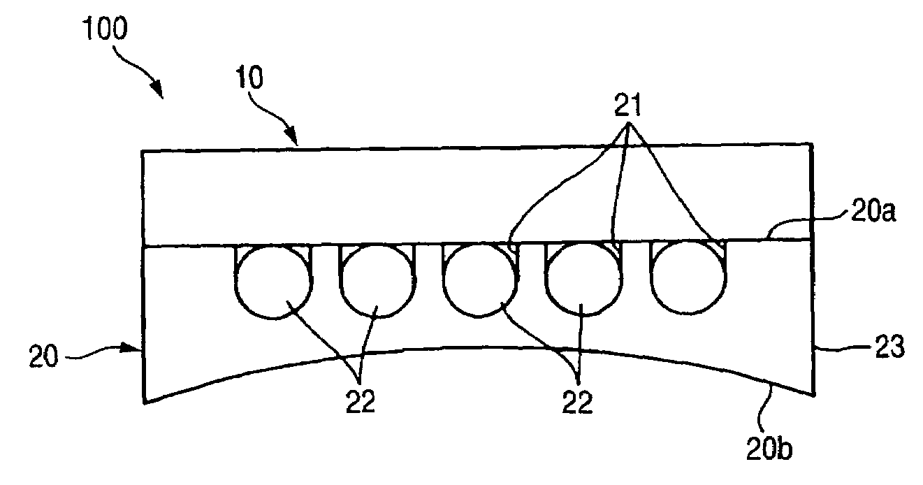
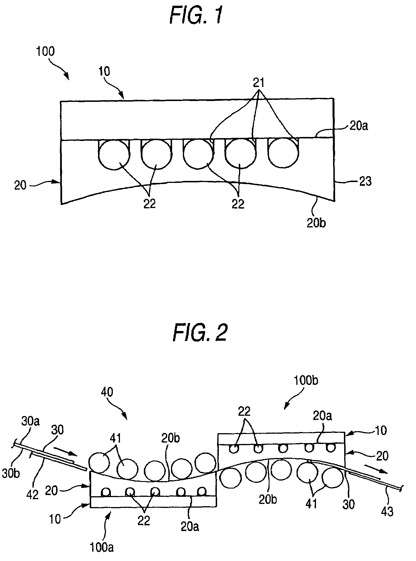
[0040]FIG. 1 is a side view to show the first embodiment according to the heating plate and the process of producing the same of the invention; and FIG. 2 is a side view to show an application example for heating the both surfaces of a heat development recording material while arranging heating plates.

[0041]As illustrated in FIG. 1, a heating plate 100 as one embodiment of the invention is provided with a heating member 10 and a guide member 20; one surface 20a of the guide member 20 is heated by the heating plate 10; and a heat development recording material 30 (see FIG. 2) as a body to be heated is heated while making the other surface 20b of the guide member 20 work as a heating surface.

[0042]As the heating member 10, a rubber heater as illustrated in FIG. 5 as described later can be used. However, any kind of heating elements can be utilized so far as they fall within the gist of the invention.

[0043]As illustrated in FIG. 1, the guide member 20 is made of, for example, a metal p...

second embodiment

[0060]Next, the heating plate according to the invention will be described below.

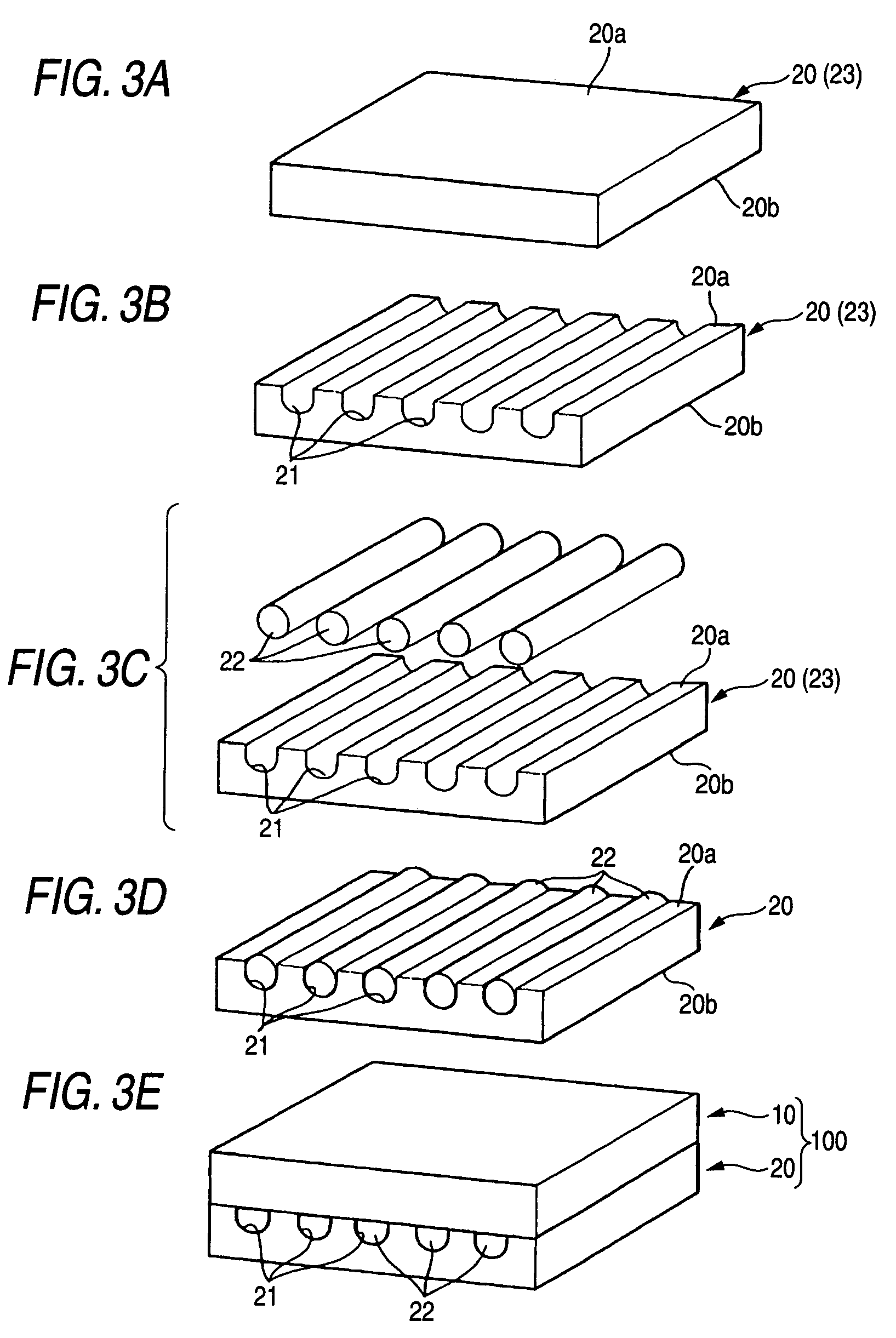
[0061]FIG. 7 is a side view to show the second embodiment according to the heating plate and the process for producing the same of the invention; FIG. 8A to FIG. 8E are each an explanatory view to show the process for producing a heating plate according to the invention; and FIG. 9A to FIG. 9C are each a cross-sectional view to show the state in which a rubber heater goes around a heat pipe. Incidentally, common sites to those in the foregoing first embodiment are each given the same symbol, and their overlapping explanations are omitted.

[0062]As illustrated in FIG. 7, this embodiment is identical to the foregoing first embodiment in the points that a heating plate 200 is provided with a heating member 10 and a guide member 20; that one surface 20a of the guide member 20 is heated by the heating member 10; and that a heat development recording material 30 (see FIG. 2) is heated while making the other su...


PUM


Abstract

A heating plate provided with: a heating member; and a guide member, one surface of which comes into contact with the heating member and the other surface of which comes into contact with a body to be heated to heat the body to be heated, wherein plural grooves are provided at prescribed intervals on the one surface of the guide member, and a heat pipe is accommodated in the groove.

Description

[0001]This application is based on Japanese Patent application JP 2004-053090, filed Feb. 27, 2004, the entire content of which is hereby incorporated by reference.BACKGROUND OF THE INVENTION[0002]1. Technical Field of the Invention[0003]The present invention relates to a heating plate for heating a body to be heated and to a process for producing the same.[0004]2. Description of the Related Art[0005]Soaking heating plates to be used for making the temperature distribution, in the widthwise direction in, for example, a fixing roll in an electronic copying machine, uniform have hitherto been disclosed (for example, see JP-UM-A-58-154378 (FIG. 1)).[0006]In one example shown in FIG. 12, a heating plate 1 has a metal plate 2 having, for example, a rectangular cross-sectional shape and made of aluminum, etc., and plural communicating holes 3 are bored in parallel to a front surface 2b or a rear surface 2c from a side surface 2a of the metal plate 2. In each of the communicating holes 3, ...

Claims


Application Information

Patent Timeline
Patent Type & Authority Patents(United States)
IPC IPC(8): H05B3/44H05B3/02F28D15/02G03D13/00H05B1/00
CPCG03D13/002F28D15/0275
Inventor TORISAWA, NOBUYUKI
Owner FUJIFILM CORP
Features
  • R&D
  • Intellectual Property
  • Life Sciences
  • Materials
  • Tech Scout
  • Unparalleled Data Quality
  • Higher Quality Content
  • 60% Fewer Hallucinations
Learn More