Supercharge Your Innovation With Domain-Expert AI Agents!

Printhead with variable exposure width

a printhead and exposure width technology, applied in printing and other directions, can solve the problems of limiting the speed of the printing device, unable to run a reduced image area at a higher speed without increasing the data rate of flow, and the fixed width cannot be used to narrower product applications. the effect of data robustness, improved data bandwidth and overall speed of the printhead

Inactive Publication Date: 2007-06-26
EASTMAN KODAK CO
View PDF9 Cites 0 Cited by
  • Summary
  • Abstract
  • Description
  • Claims
  • Application Information

AI Technical Summary

Benefits of technology

This solution enhances printhead speed and data robustness by reducing unnecessary data transmission, enabling faster printing and compatibility with multiple product widths by allowing software-adjustable active exposure areas.

Problems solved by technology

This redundant operation to load unused LEDs with zero data wastes a significant amount of data loading bandwidth and therefore limits the speed of the printing device.
It is not practical to use a wider LED printhead for narrower product applications due to-unnecessary data loading and bandwidth loss.
Fixed width does not allow for running a reduced image area at a higher speed without increasing the data rate of flow.
Known LED image path driving systems can easily be adapted to a change in the amount of data sent, but cannot easily increase the speed at which the data is sent.
As discussed, this reduces the speed of the printing device.

Method used


Image

  • Printhead with variable exposure width
  • Printhead with variable exposure width
  • Printhead with variable exposure width

Examples


Embodiment Construction

[0015]One embodiment of the present invention is a flexible width LED printhead that allows for a variable printhead imaging width by disabling unused LEDs.

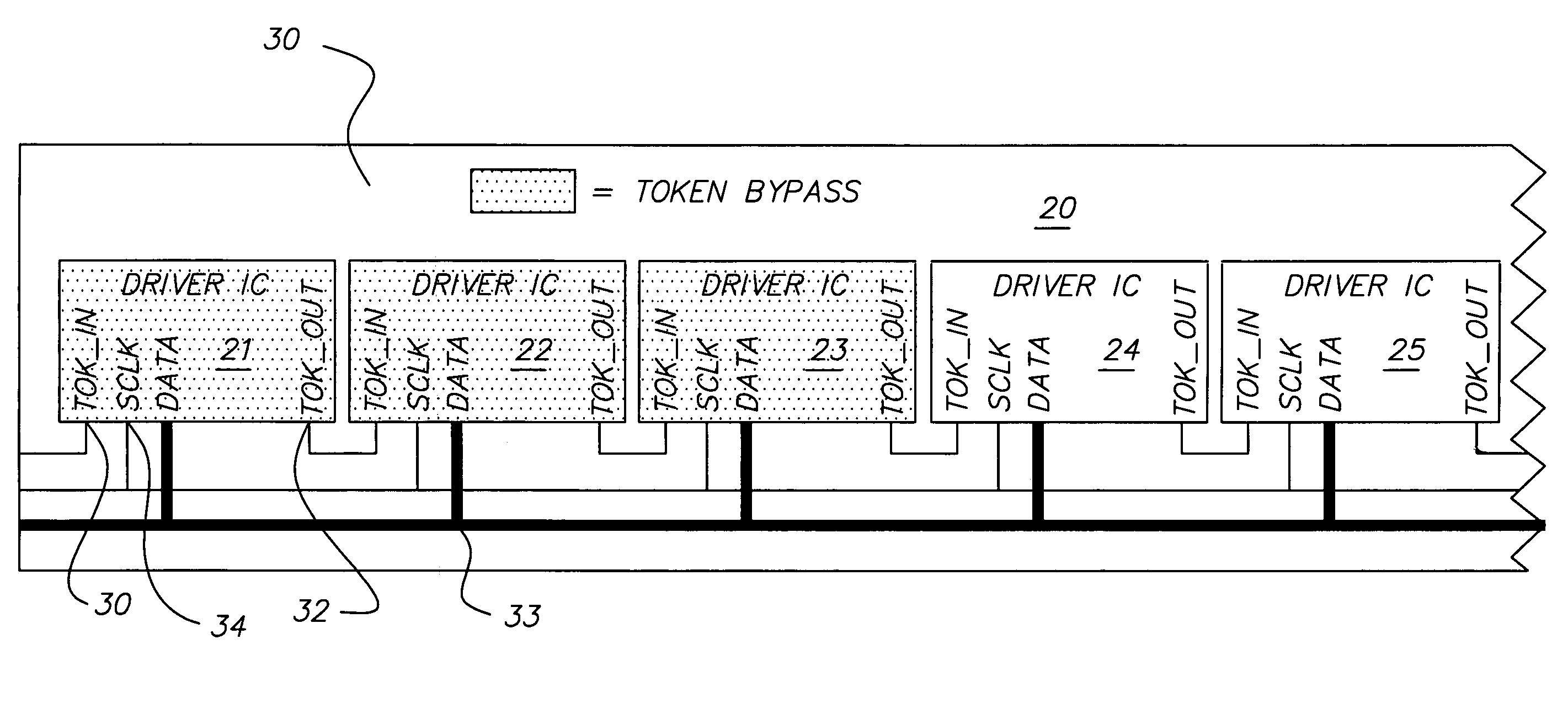
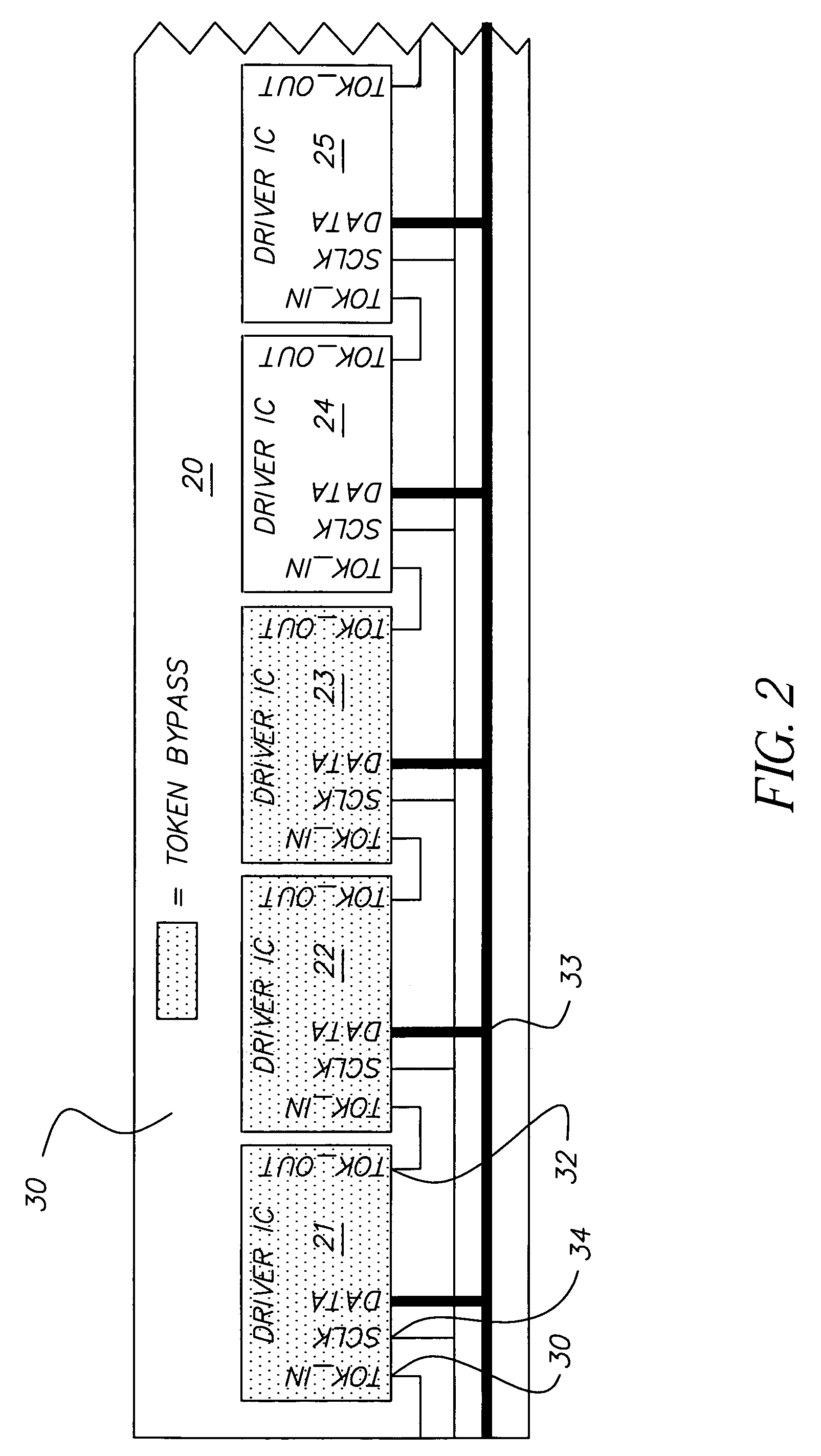
[0016]FIG. 2 is a block diagram of a portion of an LED printhead board 20 illustrating one embodiment of the present invention. Printhead board 20 includes a substrate 30 and a string of driver ICs 21-25 mounted on substrate 30. Each driver IC 21-25 is coupled to LEDs (not shown) or other types of exposure elements. In other embodiments, printhead board 20 will include more than five driver ICs, depending on the desired width of the printhead. In one embodiment, each driver IC on board 20 is coupled to 96 LEDs, and each driver IC is approximately ⅓ inch long.

[0017]In one embodiment, each driver IC 21-25 includes a token input 31, a token output 32, a clock input (“SCLK”) 34, and a data input / output bus 33. Data bus 33 maybe at the “front” of the driver ICs, as shown in FIG. 2, or it may be on the side of the driver ICs. In one em...


PUM


Abstract

A printhead with a variable exposure width having a plurality of exposure elements defining a given exposure width. A plurality of driver ICs are coupled to the exposure elements, each driver IC including a plurality of registers. A data bus is coupled to the plurality of driver ICs. Circuitry is provided in a first driver IC of the plurality of driver ICs for having data received from the data bus bypass the plurality of registers in the first driver IC to disable unused exposure elements of the plurality of exposure elements, whereby the exposure width can be varied from the given width, and data loading bandwidth is minimized.

Description

CROSS REFERENCE TO RELATED APPLICATION[0001]Reference is made to and priority claimed from U.S. Provisional Application Ser. No. 60 / 532,288, filed Dec. 23, 2003, entitled A METHOD FOR TESTING A PLASTIC SLEEVE FOR AN IMAGE CYLINDER OR A BLANKET CYLINDER.FIELD OF THE INVENTION[0002]The present invention is directed to electronic digital printing devices. More particularly, the present invention is directed to an electronic printhead having a variable exposure width.BACKGROUND OF THE INVENTION[0003]Many electronic digital printers apply print characters to paper via multiple exposure elements of an exposure device. In some printers, such as the NexPress 2100 from NexPress Solutions LLC, the exposure elements are light emitting diodes (“LEDs”) and the exposure device is an LED printhead.[0004]The LEDs are typically controlled by a printhead driver integrated circuit (“IC”). Each driver IC may control many LEDs, and a printer may include multiple driver ICs.[0005]Known LED printhead asse...

Claims


Application Information

Patent Timeline
Patent Type & Authority Patents(United States)
IPC IPC(8): B41J2/47B41J2/435B41J2/45
CPCB41J2/45
Inventor O'HARA, SHAWN E.REILLY, DENIS P.
Owner EASTMAN KODAK CO
Features
  • R&D
  • Intellectual Property
  • Life Sciences
  • Materials
  • Tech Scout
  • Unparalleled Data Quality
  • Higher Quality Content
  • 60% Fewer Hallucinations
Learn More