Supercharge Your Innovation With Domain-Expert AI Agents!

Joint connector and method of assembling it

a technology of connectors and connectors, applied in the direction of connection, electrical apparatus, coupling device connection, etc., can solve the problem that the connectors do not significantly resist the insertion of the terminal fittings, and achieve the effect of reducing the number of parts

Inactive Publication Date: 2007-07-10
SUMITOMO WIRING SYST LTD
View PDF11 Cites 68 Cited by
  • Summary
  • Abstract
  • Description
  • Claims
  • Application Information

AI Technical Summary

Benefits of technology

[0008]The joint terminal is held at the first position while the terminal fittings are being inserted into the housing. Thus, the joint terminal does not significantly resist insertion of the terminal fittings. The joint terminal is moved to the second position after the terminal fittings have been inserted into the housing. Thus, the joint terminal contacts and shorts the terminal fittings in the housing. The joint terminal is mounted in the housing without a separate holder. As a result, the number of parts can be reduced.

Problems solved by technology

Thus, the joint terminal does not significantly resist insertion of the terminal fittings.

Method used


Image

  • Joint connector and method of assembling it
  • Joint connector and method of assembling it
  • Joint connector and method of assembling it

Examples


Embodiment Construction

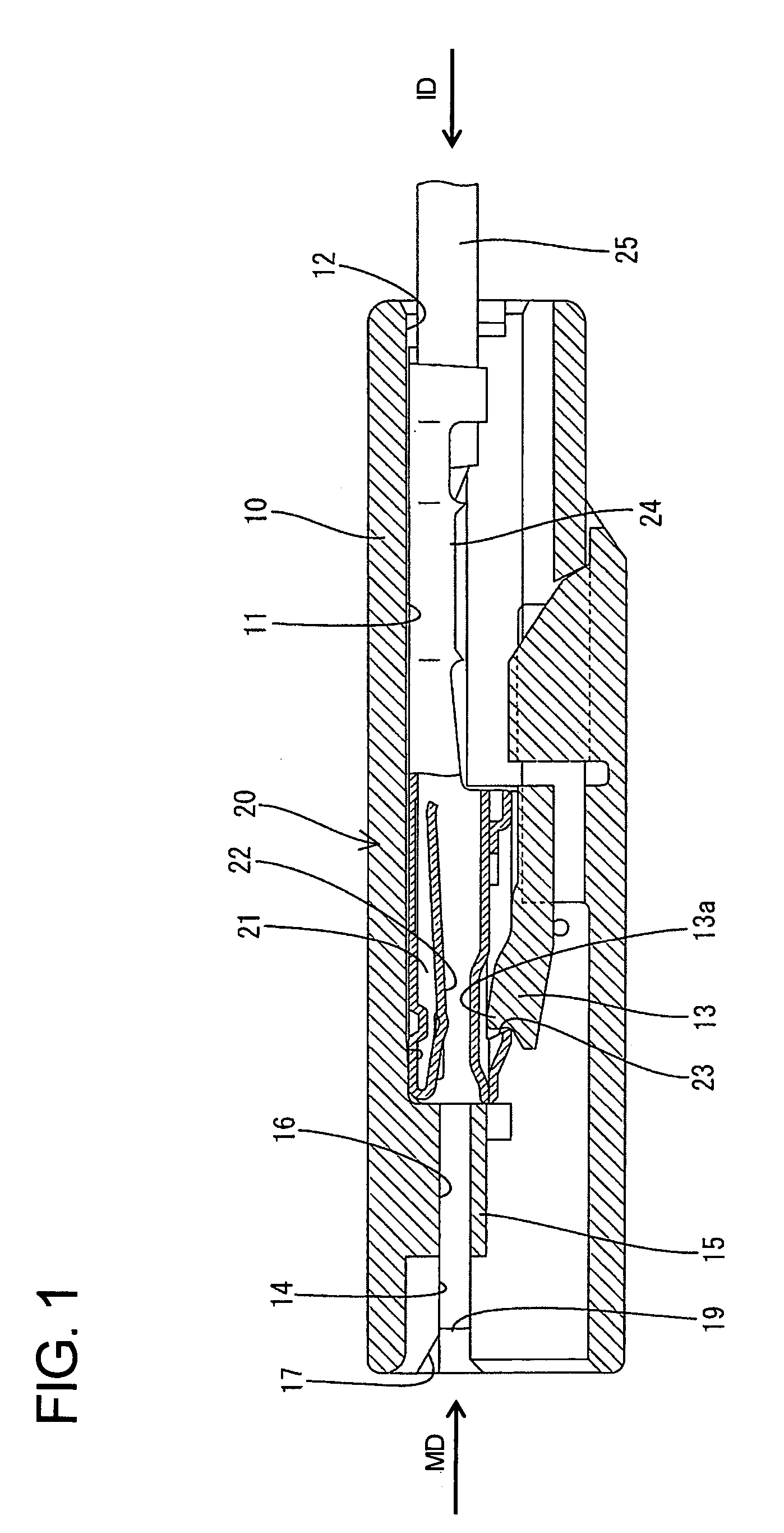
[0024]A joint connector according to the invention has a housing identified by the numeral 10 in FIGS. 1 to 6. The housing 10 is made e.g. of a synthetic resin and is substantially in the form of a flat block with opposite front and rear ends. Long narrow cavities 11 extend through the housing 10 in forward and backward directions and are arranged substantially side by side along a transverse direction TD. A terminal insertion opening 12 extends into each cavity 11 at the rear end of the housing 10. Locks 13 are formed unitarily with the housing 10 and are cantilevered forward along the bottom wall of the respective cavities 11. Each lock 13 is resiliently deformable up and down towards and away from the respective cavity 11.

[0025]A wide slit-shaped guiding groove 14 is formed in the front end surface of the housing 10 and extends across a transverse area corresponding to the cavities 11. Upper and lower surfaces of the guiding groove 14 are flat and extend substantially parallel to...


PUM


Abstract

A joint connector has a housing (10) with insertion spaces (11) for receiving terminal fittings (20). A joint terminal (30) is mounted in the housing (10) at a first position where the joint terminal (30) is retracted from the insertion spaces (11). The terminal fittings (20) then are inserted into the insertion spaces (11) of the housing (10). The joint terminal (30) then is displaced to a full locking position for contacting and shorting the terminal fittings (20). As a result, the joint terminal (30) does not hinder insertion of the terminal fittings (20). Furthermore, the joint terminal (30) is mounted directly in the housing (10) and does not require a separate holder. Thus, the number of parts is reduced.

Description

BACKGROUND OF THE INVENTION[0001]1. Field of the Invention[0002]The invention relates to a joint connector and to a method of assembling it.[0003]2. Description of the Related Art[0004]U.S. Pat. No. 6,878,017 discloses a joint connector that has a housing and a plurality of terminal fittings mounted in the housing. A joint terminal is mounted in a holder and has a plurality of contact portions. The contact portions can be brought into contact with the terminal fittings in the housing to short the terminal fittings.[0005]The number of parts of the joint connector could be reduced by eliminating the holder and mounting the joint terminal in the housing. However, a connection resistance is produced between the joint terminal and the terminal fittings when the terminal fittings are inserted into the housing and creates a reaction force against the insertion. The terminal fittings often are inserted into the housing by gripping wires connected with the terminal fittings. However, the abo...

Claims


Application Information

Patent Timeline
Patent Type & Authority Patents(United States)
IPC IPC(8): H01R31/08
CPCH01R31/08H01R31/085
Inventor SAKURAI, TOSHIKAZUSAKATANI, ATSUSHI
Owner SUMITOMO WIRING SYST LTD
Features
  • R&D
  • Intellectual Property
  • Life Sciences
  • Materials
  • Tech Scout
  • Unparalleled Data Quality
  • Higher Quality Content
  • 60% Fewer Hallucinations
Learn More