Capacitor applicable to a device requiring large capacitance

a technology of capacitors and capacitances, applied in the field of capacitors, can solve the problems of low reliability of capacitors, difficult to stably obtain desired effective dielectric constants, and capacitors with a large amount of fine particles in the dielectric layer, so as to achieve the effect of increasing the apparent dielectric constant, increasing the capacitance of capacitors, and decreasing the effective thickness of the dielectric layer

Active Publication Date: 2007-07-17
ALPS ALPINE CO LTD
View PDF11 Cites 10 Cited by
  • Summary
  • Abstract
  • Description
  • Claims
  • Application Information

AI Technical Summary

Benefits of technology

[0008]With this structure, the surface area of the pseudo electrode layer increases since the conductive particles are contained in the pseudo electrode layer. Thus, the integrated electrode area of the pseudo electrode layer and the electrode is increased, thereby increasing the capacitance of the capacitor as a whole. Moreover, since the dielectric layer containing metal fine particles do not undergo percolation, as described in FIG. 7, high reliability can be achieved.
[0010]Preferably, the dielectric layer of the capacitor contains the conductive particles or ceramic particles. The effective thickness of the dielectric layer can be decreased, and the apparent dielectric constant can be increased when the dielectric layer contains the conductive particles. The substantial dielectric constant of the dielectric component can be increased when the dielectric layer contains the ceramic particles. As a result, the capacitance of the capacitor can be increased.
[0011]More preferably, the dielectric layer contains insulating particles to increase the resistance to moisture absorption and thereby prevent degradation of characteristics due to moisture absorption.
[0012]Preferably, the first pseudo electrode layer is composed of a material having a dielectric constant equal to or larger than a dielectric constant of a material constituting the dielectric layer. In this manner, serial connection between the dielectric material of the dielectric layer and the dielectric material of the pseudo electrode layer can be prevented, and a decrease in capacitance can be avoided.

Problems solved by technology

However, recent trends of faster digital circuits require capacitors to have ever larger capacitance.
In this percolation region, as shown in FIG. 7, the change in dielectric constant shows a steep profile, and it is thus difficult to stably obtain a desired effective dielectric constant.
Thus, a capacitor including a large amount of fine particles in the dielectric layer has a problem of low reliability.
The problem of percolation does not occur when the dispersed particles are dielectric particles, such as ceramic fine particles; however, the upper limit of the dielectric constant is limited by the dielectric constant of the ceramic fine particles dispersed.
This makes it difficult to fabricate a capacitor with large capacitance.

Method used


Image

  • Capacitor applicable to a device requiring large capacitance
  • Capacitor applicable to a device requiring large capacitance
  • Capacitor applicable to a device requiring large capacitance

Examples


first embodiment

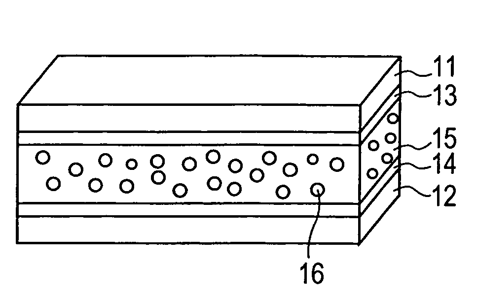
[0021]FIG. 1 shows a first embodiment of a capacitor of the present invention. The capacitor includes a pair of electrodes 11 and 12 having main surfaces opposing each other, pseudo electrode layers 13 and 14 disposed on the main surfaces of the electrodes 11 and 12, and a dielectric layer 15 interposed between the pseudo electrode layers 13 and 14. In this embodiment, both the electrodes 11 and 12 are provided with the pseudo electrode layers. Alternatively, a pseudo electrode layer may be provided to only one of the electrodes 11 and 12.

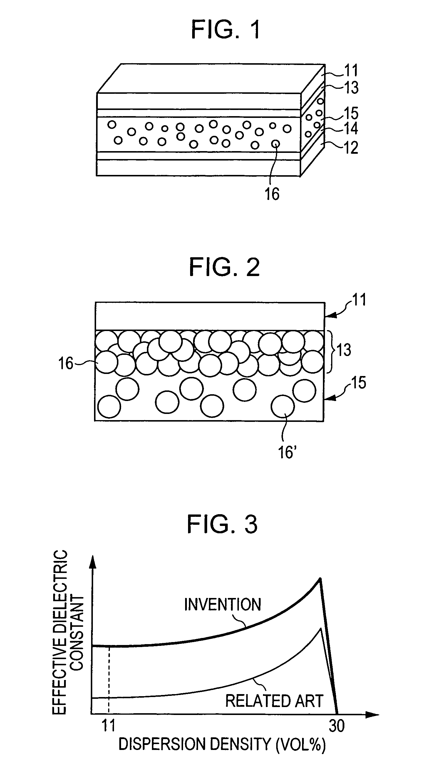
[0022]The electrodes 11 and 12 may be conventional electrodes for capacitor applications. The pseudo electrode layers 13 and 14 are arranged as shown in FIG. 2. The pseudo electrode layers 13 and 14 (only the pseudo electrode layer 13 is shown in FIG. 2) contain conductive particles 16 that electrically couple with the electrodes 11 and 12 (only the electrode 11 is shown in FIG. 2). In this pseudo electrode layer 13, the conductive particles 16 are...

second embodiment

[0037]In this embodiment, insulating particles are contained in the dielectric layer. FIG. 5 shows a capacitor according to a second embodiment of the present invention. In FIG. 5, the same components as those shown in FIG. 1 were represented by the same reference numerals, and the detailed description of these identical components are omitted to avoid redundancy.

[0038]The capacitor shown in FIG. 5 includes a dielectric layer 15 containing both conductive particles 16 and insulating particles 17. In this manner, the resistance of the capacitor against moisture absorption can be increased, and degradation of characteristics due to moisture absorption can be prevented. For example, when the dielectric layer 15 is composed of a polymeric material, it is possible that the polymer absorbs moisture, thereby adversely affecting the characteristics. By dispersing the insulating particles 17 into the dielectric layer 15, the percentage of the polymer can be decreased as the polymer is replac...

examples

[0041]Experiments described below were conducted to confirm the advantages of the present invention.

[0042]A capacitor having electrodes 11 and 12 composed of aluminum, pseudo electrode layers 13 and 14 composed of a polyimide resin (dielectric constant: 3.5) and silver particles (conductive particles 16) having an average diameter of about 0.1 μm (content: about 40 vol %), and a dielectric layer 15 composed of a polyimide resin, silver particles (conductive particles 16′) having an average particle diameter of about 0.1 μm (content: about 10 vol %) and alumina particles (insulating particles 17, dielectric constant: 9 to 10) having an average particle diameter of about 0.1 μm (content: about 40 vol %) was prepared as described above. The thickness of the dielectric layer 15 was 10 μm, and the electrode area was 100 μm×100 μm. The pseudo electrode layers 13 and 14 and the dielectric layer 15 were baked at about 150° C. for 10 minutes. The effective dielectric constant of this capacit...


PUM


Abstract

A capacitor includes a first electrode and a second electrode arranged so that a main surface of the first electrode opposes a main surface of the second electrode, a first pseudo electrode layer disposed on the main surface of the first electrode, and a dielectric layer disposed between the first pseudo electrode layer and the main surface of the second electrode. The first pseudo electrode layer includes conductive particles electrically coupled to the first electrode.

Description

BACKGROUND OF THE INVENTION[0001]1. Field of the Invention[0002]The present invention generally relates to capacitors and particularly to a capacitor applicable to a device requiring particularly large capacitance.[0003]2. Description of the Related Art[0004]Attempts have been made to increase the capacitance of a capacitor having a dielectric layer interposed between a pair of electrodes. There are several techniques for increasing the capacitance of the capacitor: by increasing the dielectric constant of the dielectric material constituting the dielectric layers, by decreasing the interelectrode distance, and / or by increasing the electrode areas. One of such attempts is a capacitor including a dielectric layer composed of a dielectric material, such as a polymeric material, and conductive or ceramic fine particles having a diameter less than 1 μm dispersed in the dielectric material (refer to U.S. Pat. No. 6,544,651 and US Patent Application No. 20030006402). An example of this ca...

Claims


Application Information

Patent Timeline
Patent Type & Authority Patents(United States)
IPC IPC(8): H01L29/00
CPCH01G4/008H01G4/14H01G4/20
Inventor AIHARA, MASAMI
Owner ALPS ALPINE CO LTD
Why Eureka
Try Eureka