Check patentability & draft patents in minutes with Patsnap Eureka AI!

Apparatus for testing a memory module

a memory module and apparatus technology, applied in the direction of electronic circuit testing, measurement devices, instruments, etc., can solve the problems of inability to access individual subelements of the module with very great difficulty, inability to examine the cause of faults furthermore, and inability to test the cause of faults particularly efficiently and thoroughly

Inactive Publication Date: 2007-07-17
POLARIS INNOVATIONS LTD
View PDF16 Cites 8 Cited by
  • Summary
  • Abstract
  • Description
  • Claims
  • Application Information

AI Technical Summary

Benefits of technology

Enables thorough and efficient testing of memory modules by allowing direct access to test modes and extreme conditions, facilitating rapid identification of faults and improving test depth, especially during the booting phase.

Problems solved by technology

The examination of the cause of fault is problematic since generally the interaction between motherboard and module cannot be examined without intervening in the basic functions of the motherboard, whereby the measurement results are in turn corrupted.
The examination of the cause of a fault is furthermore made more difficult by the fact that, by virtue of the module being incorporated into the system, the individual subelements of the module can be accessed only with very great difficulty.
Since the motherboard can only be operated in a well-defined and prescribed operating mode, however, it is not possible to carry out tests, which put the memory modules into an extreme state.
By way of example, there is no known possibility of altering the timing of the chips situated on the module, of applying particularly high voltages or else, for example in the case of memory modules, of carrying out tests for determining the storage time, since the motherboard is not designed to operate with such extreme states and, therefore, does not actually permit the latter at all.
Since most faults occur during the start-up of the system, the analysis socket is only of limited use.
A further problem consists in the fact that in the booting phase, in which most application problems usually occur, a mode register set is performed by means of which the bits that specify the operating state of the individual chips are set to predetermined values.
Accordingly, it is not possible to test a module during the start-up of the computer in a test mode.

Method used


Image

  • Apparatus for testing a memory module
  • Apparatus for testing a memory module
  • Apparatus for testing a memory module

Examples


Embodiment Construction

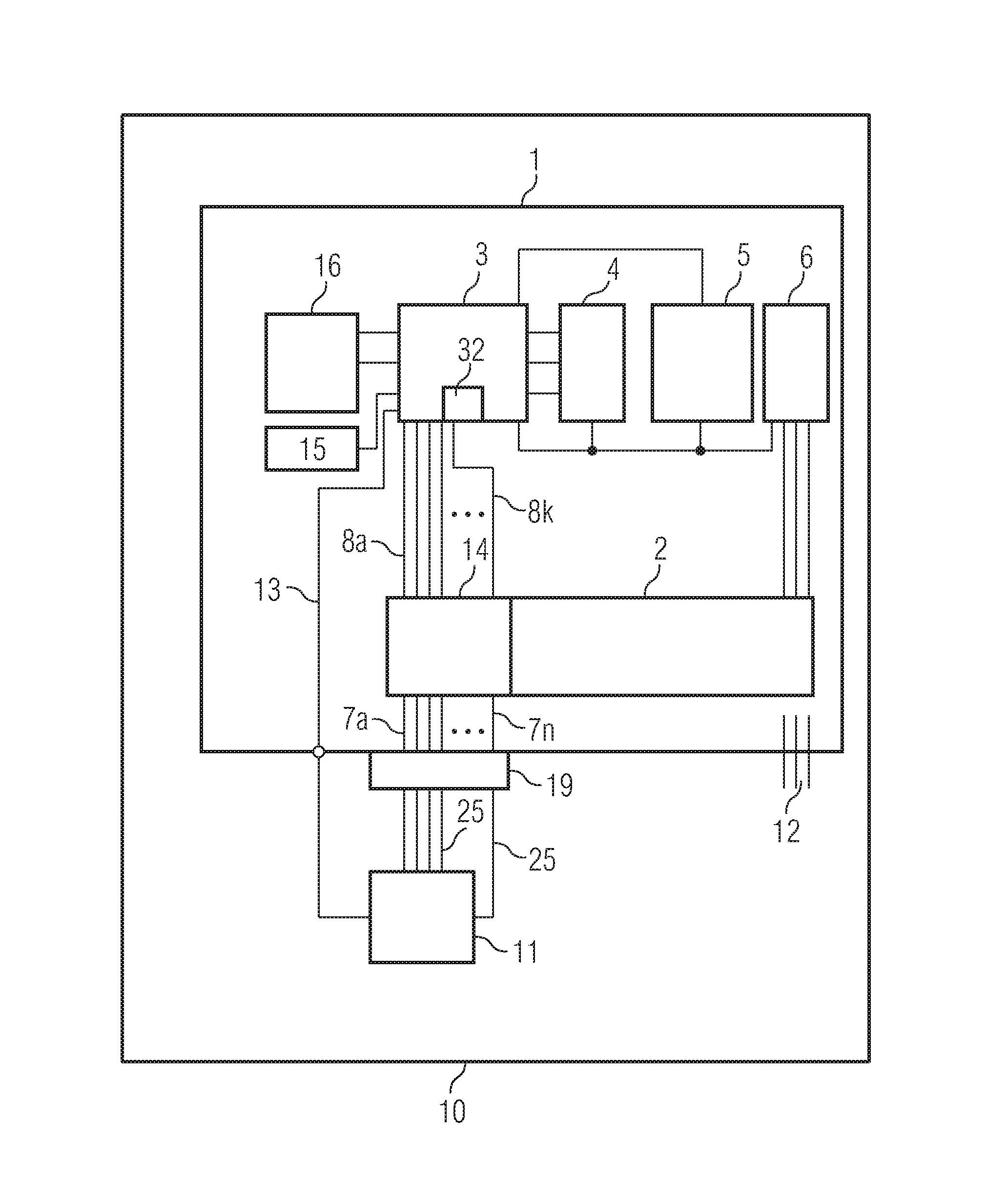
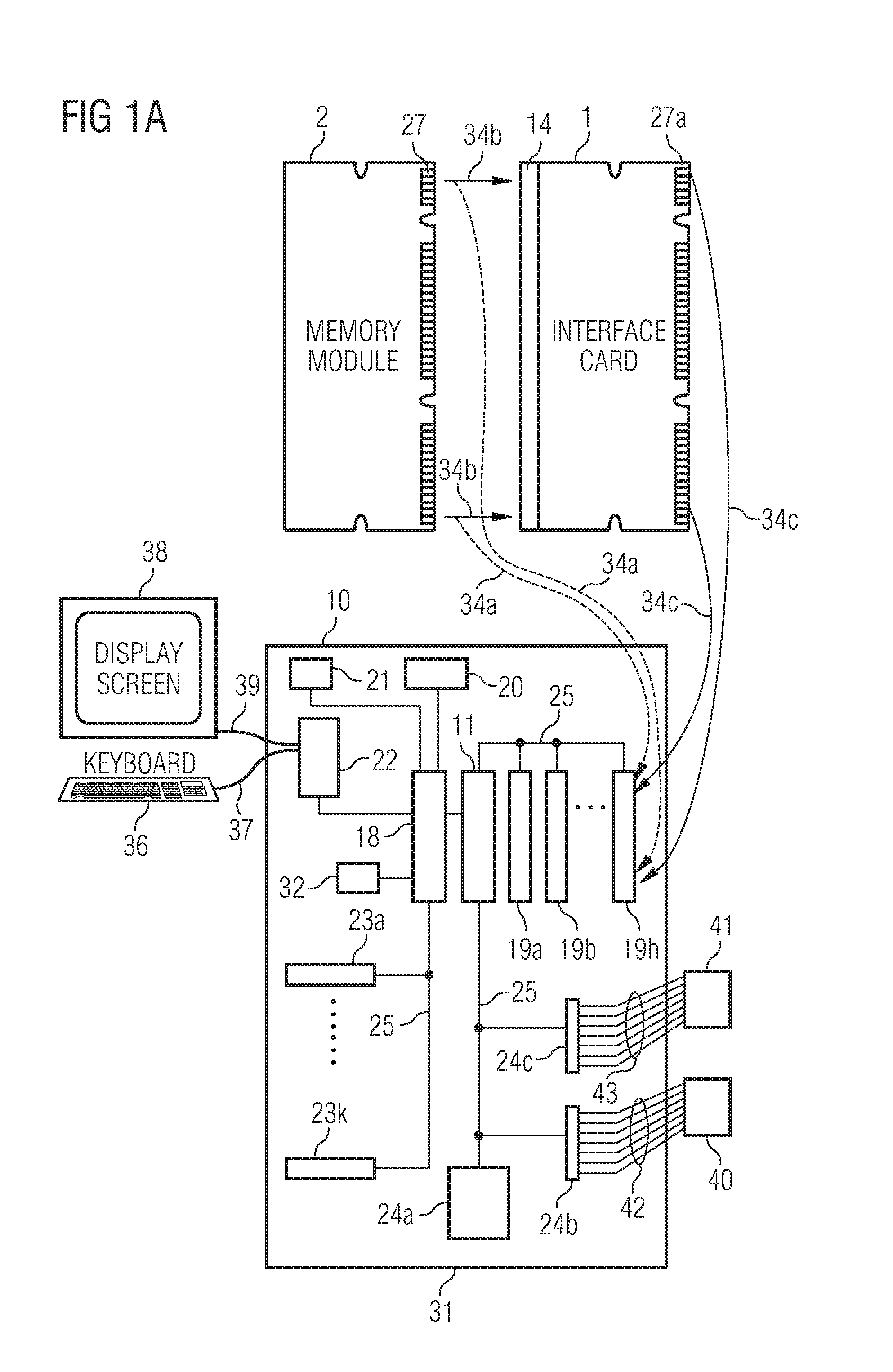
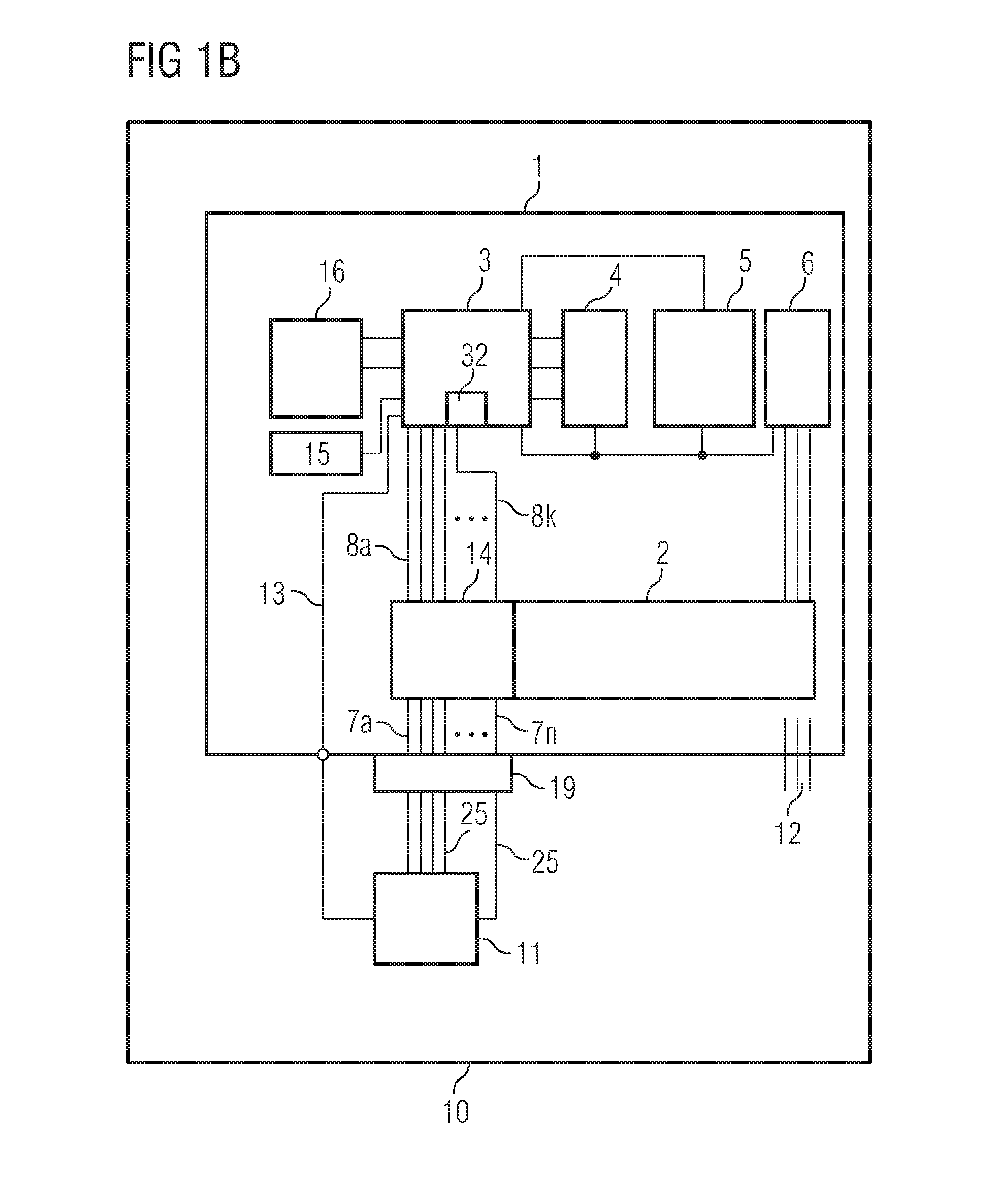
[0041]In its lower part, FIG. 1A shows a schematic view of a motherboard of a computer. The motherboard 10 is essentially a circuit board arrangement with a processor-based data processing device. The latter comprises, inter alia, a processor 17, a memory device 18, a clock generator 20 and a bus 25 for the exchange of signals among the system components. Data, addresses, operating commands and control signals are transferred via the bus. For the exchange of signals between the processor 17 and a main memory, the processor 17 drives the chip set 11, which converts the specified memory address into a memory module address and transmits corresponding commands to the corresponding memory module 2 via the data bus 25. The memory module 2 is part of the main memory of the motherboard 10. During the communication between memory module 2 and processor 17, the signals are thus exchanged between memory module 2 and chip set 11. During normal operation, memory module 2 connects directly to th...


PUM


Abstract

An apparatus (1) for testing a memory module (2) suitable for exchanging electrical signals with a motherboard (10) contains a device (8a–8k) suitable for detecting the operating state of at least one semiconductor chip (26a–26m) of the module, which device comprises a first set of signal lines (8a–8k), a microcontroller (3) with a memory device (32) for storing the operating state, said microcontroller being electrically connected to the signal lines (8a–8k), a clock generator (5) suitable for generating an operating clock, said clock generator being electrically connected to the microcontroller (3), and a signal connection (13) suitable for communicating a signal for controlling access to the memory module (2) between the circuit board arrangement (10) and the microcontroller (3) and for communicating to the microcontroller (3) a signal for initiating a process of detecting the operating state.

Description

[0001]This application claims priority to German Patent Application 103 44 877.2, which was filed Sep. 26, 2003, and is incorporated herein by reference.TECHNICAL FIELD[0002]The present invention relates to an apparatus for testing a memory module.BACKGROUND[0003]Memory modules are used, for example, to provide main memory for a processor-based data processing architecture.[0004]FIG. 3 shows a plan view of an exemplary memory module 2 that can be tested with the apparatus according to the invention. A memory module 2 of this type comprises a circuit board 28 and also at least two memory chips 26a–26m arranged thereon. A plurality of memory chips 26a–26m, for example 8, 10, 18 or 36, are usually applied on a circuit board or printed circuit board 28 of this type, it being possible for both the front side and the rear side of the circuit board to be populated. Examples of memory chips 26 comprise SDRAM or DDR SDRAM (“Double Data Rate Synchronous Dynamic Random Access”), memory chips a...

Claims


Application Information

Patent Timeline
Patent Type & Authority Patents(United States)
IPC IPC(8): G11C29/00G11C29/56
CPCG11C29/56G11C2029/0407G11C2029/5602
Inventor STOCKEN, CHRISTIANSOMMER, MICHAEL BERNHARD
Owner POLARIS INNOVATIONS LTD
Features
  • R&D
  • Intellectual Property
  • Life Sciences
  • Materials
  • Tech Scout
  • Unparalleled Data Quality
  • Higher Quality Content
  • 60% Fewer Hallucinations
Learn More