Supercharge Your Innovation With Domain-Expert AI Agents!

Micro-cavity laser having increased sensitivity

a micro-cavity laser and laser technology, applied in the field of optical cavities, can solve the problems of low sensitivity of optical devices to applied electrical signals, and the overall dimensions of electro-optic materials used in optical devices are small

Inactive Publication Date: 2007-07-31
TEKTRONIX INC
View PDF14 Cites 18 Cited by
  • Summary
  • Abstract
  • Description
  • Claims
  • Application Information

AI Technical Summary

Benefits of technology

The design significantly increases the sensitivity of the micro-cavity laser to applied electrical signals, allowing for more precise control over optical output pulses and frequency modulation.

Problems solved by technology

Currently, the minimum overall dimensions of the electro-optic material used in optical devices and cavities is limited by the practical size at which the material can be handled resulting in electrodes that are positioned at a substantial distance from the optical path of the optical signal.
This results in optical devices having low sensitivity to the applied electrical signal.

Method used


Image

  • Micro-cavity laser having increased sensitivity
  • Micro-cavity laser having increased sensitivity
  • Micro-cavity laser having increased sensitivity

Examples


Embodiment Construction

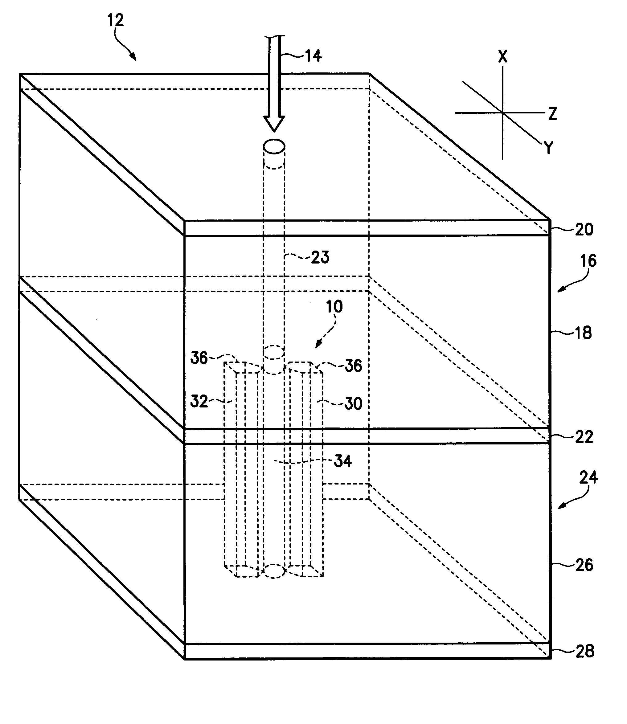
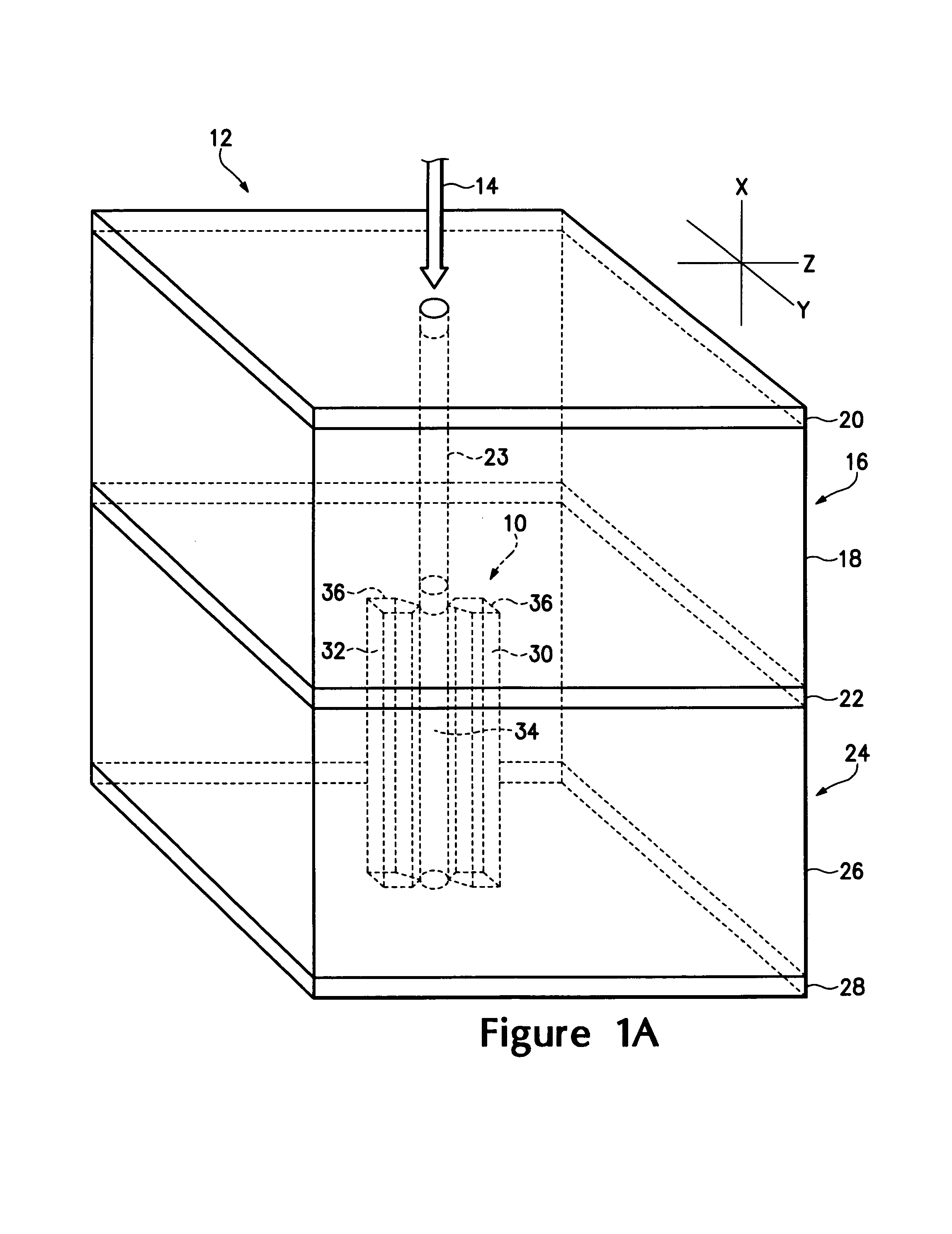
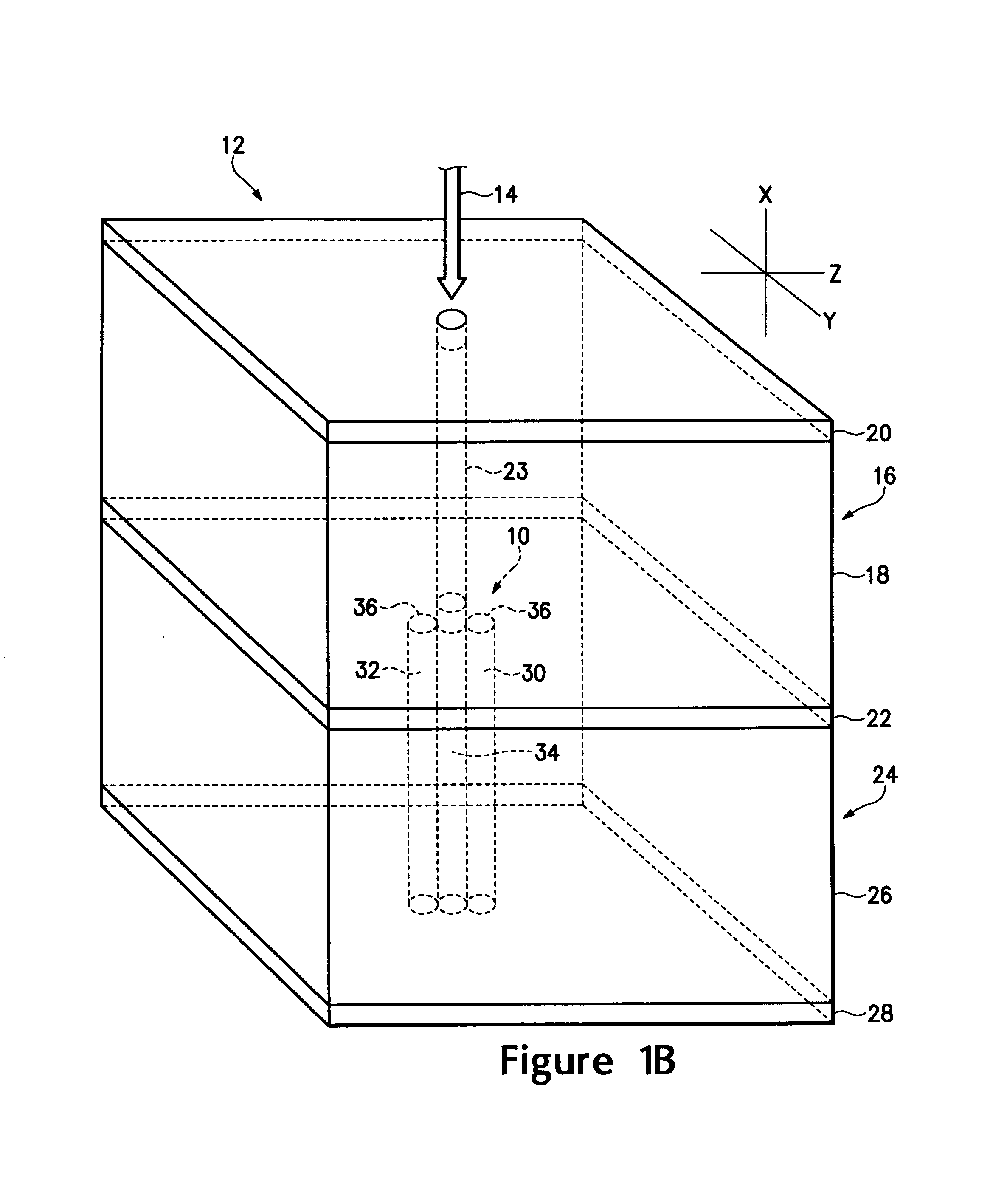
[0015]Referring to FIGS. 1A, 1B and 1C, there are shown various electrodes structures 10 usable in a micro-cavity laser 12 receiving an optical signal 14. The micro-cavity laser 12 has a gain cavity 16 having an active gain medium 18 disposed between two optically reflective materials 20 and 22. The active gain medium 18 generates a coherent, polarized optical output 23 when pumped by an coherent optical input, such as the optical signal 14. An optical resonant cavity 24 is coupled to the gain cavity 16 and has an electro-optic material 26 disposed between opposing optical reflective materials 22 and 28 where the optically reflective material 22 is common to the two cavities. The optically reflective materials 20, 22 and 28 are preferably ceramic mirrors formed from layers of zirconium dioxide, silicon dioxide and silicon nitride. It is important in certain applications that the optically reflective materials be non-metallic to reduce capacitive and inductive effects. The reflectivi...


PUM


Abstract

An optically pumped micro-cavity laser has an optical gain cavity and an optical resonant cavity. The optical gain cavity has a gain medium disposed that generates an optical output in response to an optical pump signal. The optical resonant cavity has an electro-optic material in which is disposed an electrode structure with first and second apertures disposed generally parallel to an optical signal propagating within the electro-optic material. Electrically conductive material is disposed within the apertures coupling an electrical signal to the optical cavity. Optically reflective material is disposed on the opposing surfaces of the micro-cavity laser and between the optical gain cavity and the optical resonant cavity.

Description

CROSS-REFERENCE TO RELATED APPLICATION[0001]This application claims the benefit of the U.S. Provisional Application No. 60 / 552,334, filed Mar. 10, 2004.BACKGROUND OF THE INVENTION[0002]The present invention relates generally to optical cavities and more particularly to a micro-cavity laser having increased sensitivity to applied electrical fields.[0003]U.S. Pat. No. 4,982,405 teaches a Q-switched micro-cavity laser having a first resonant cavity consisting of a gain medium disposed between two optically reflective mirrors. A second optical resonant cavity is formed by two partially reflective mirrors and is physically and optically coupled to the first resonant cavity. The first resonant cavity will lase when pumped by an external optical source. The reflectivity of the intermediate mirror common to the first and second cavities as seen by the gain medium of the first resonant cavity looking toward the second resonant cavity is determined by the resonant modes of the second resonant...

Claims


Application Information

Patent Timeline
Patent Type & Authority Patents(United States)
IPC IPC(8): H01S3/08H01S3/06H01S3/082H01S3/0941H01S3/107H01S3/115H01S3/16
CPCH01S3/0627H01S3/0604H01S3/08059H01S3/082H01S3/09415H01S3/107H01S3/115H01S3/1611H01S3/1673
Inventor YAKYMYSHYN, CHRISTOPHER P.LAW, WILLIAM Q.HAGERUP, WILLIAM A.
Owner TEKTRONIX INC
Features
  • R&D
  • Intellectual Property
  • Life Sciences
  • Materials
  • Tech Scout
  • Unparalleled Data Quality
  • Higher Quality Content
  • 60% Fewer Hallucinations
Learn More