Supercharge Your Innovation With Domain-Expert AI Agents!

Variable radial flow rate control system

Inactive Publication Date: 2007-08-21
SCHLUMBERGER TECH CORP
View PDF14 Cites 21 Cited by
  • Summary
  • Abstract
  • Description
  • Claims
  • Application Information

AI Technical Summary

Benefits of technology

Enables precise control of fluid flow rates between formation zones and the tubing string, reducing the need for multiple control lines and enhancing operational flexibility and efficiency.

Problems solved by technology

Additionally, the flow control valves are typically operated between a full-flow or full-open position and a full-closed position, and do not permit operation of selected choked flow rate positions.

Method used


Image

  • Variable radial flow rate control system
  • Variable radial flow rate control system
  • Variable radial flow rate control system

Examples


Embodiment Construction

[0020]Refer now to the drawings wherein depicted elements are not necessarily shown to scale and wherein like or similar elements are designated by the same reference numeral through the several views.

[0021]As used herein, the terms “up” and “down”; “upper” and “lower”; and other like terms indicating relative positions to a given point or element are utilized to more clearly describe some elements of the embodiments of the invention. Commonly, these terms relate to a reference point as the surface from which drilling operations are initiated as being the top point and the total depth of the well being the lowest point.

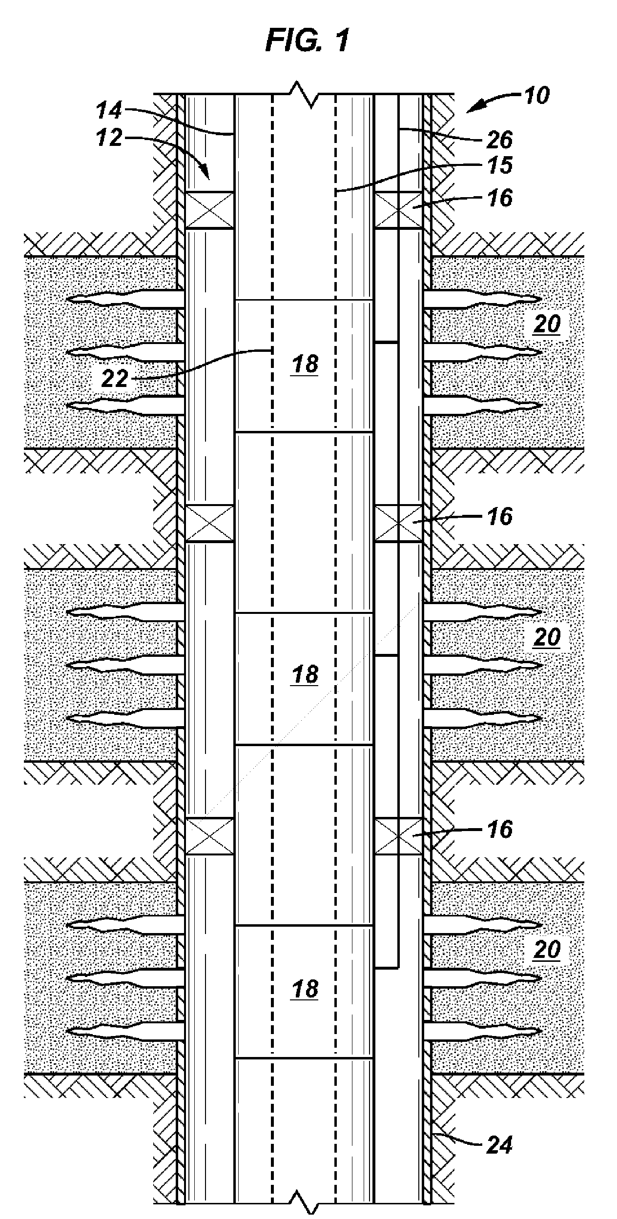
[0022]The following Figures and description provide a variable radial flow control system, having a first rotational choke member in fluid communication with a second fixed choke member. A motor end is connected to the first rotational choke member for moving the rotational choke between variable radial flow rate positions including a full-closed position, blocking fl...


PUM


Abstract

A variable radial flow rate control valve including a body forming a bore along the longitudinal axis thereof for transporting a fluid through the body, a fixed choke member fixedly positioned about the bore, the fixed choke member forming a fixed aperture, a rotational choke member rotationally positioned about the bore, the rotational choke member forming a rotational aperture radially corresponding to the fixed aperture, wherein a fluid passage is formed radially between the bore and the exterior of the body when the corresponding apertures overlap. The rotational choke member is rotatably, but not axially, moveable in relation to the fixed choke member between variable radial flow rate positions.

Description

FIELD OF THE INVENTION[0001]The present invention relates in general to a system for controlling radial flow of fluid into and / or out of a string of tubing. More particularly, the invention relates to a system for selectively controlling the radial flow rate between the tubing and the wellbore.BACKGROUND[0002]In completing a well, one or more zones may be perforated to enable production and / or injection of fluids. Completion equipment including flow control devices, tubing, packers, and other devices may be installed in various positions in the well to manage the respective zones. In operating the well it is necessary to actuate the flow control device for each zone.[0003]Typically each flow control device is actuated either hydraulically or electrically. Each flow control valve being connected to a separate hydraulic and / or electrical control line from the other flow control valves. Additionally, the flow control valves are typically operated between a full-flow or full-open positi...

Claims


Application Information

Patent Timeline
Patent Type & Authority Patents(United States)
IPC IPC(8): F16K31/00
CPCF16K5/0428E21B34/14E21B34/10E21B34/066E21B2200/02
Inventor DWIVEDI, ALOK
Owner SCHLUMBERGER TECH CORP
Features
  • R&D
  • Intellectual Property
  • Life Sciences
  • Materials
  • Tech Scout
  • Unparalleled Data Quality
  • Higher Quality Content
  • 60% Fewer Hallucinations
Learn More