Supercharge Your Innovation With Domain-Expert AI Agents!

Fluid machine

a technology of fluid machine and rotary piston, which is applied in the direction of refrigerating components, steam regeneration, rotary piston liquid engine, etc., can solve the problem of insufficient refrigerating operation and achieve the effect of improving efficiency

Inactive Publication Date: 2007-09-04
DENSO CORP +1
View PDF6 Cites 9 Cited by
  • Summary
  • Abstract
  • Description
  • Claims
  • Application Information

AI Technical Summary

Benefits of technology

[0006]It is, therefore, an object of the present invention, in view of the above mentioned problems, to provide a fluid machine which can not only satisfy a performance for a pump mode operation but also improve its efficiency for a motor mode operation, wherein the fluid machine has the pump mode operation for pressurizing and discharging fluid and the motor mode operation for converting fluid pressure during fluid expansion into energy of movement and for outputting kinetic energy.
[0008]In the above fluid machine, a volume of the working chambers of the expansion-and-compressor device is designed to be made smaller so that the expansion-and-compressor device can be operated in an optimum condition to effectively output the kinetic energy, even when volumetric flow rate is decreased due to a higher operating pressure in the motor mode operation than an operating pressure in the pump mode operation. In the case that the volume of the working chambers is reduced as above, a sufficient refrigerating operation may not be obtained when the expansion-and-compressor device is operated as the compressor device in the pump mode operation. Such a decrease of the performance of the refrigerating operation (the pump mode operation), however, can be avoided by driving the compressor device at a higher rotational speed.
[0009]According to the above feature, therefore, since the necessary discharge amount of the compressed refrigerant during the pump mode operation can be obtained by the increased rotational speed, even when the capacity per revolution of the expansion-and-compressor device is set to a smaller amount. As a result, since the expansion-and-compressor device can be operated with the capacity suitable for the volumetric flow rate of the refrigerant in the motor mode operation, the decrease of the rotational speed can be avoided and thereby the influence of the leak per revolution can be reduced (by making the expansion speed higher than the leak speed of the refrigerant) to finally improve the operational efficiency of the fluid machine.
[0010]Accordingly, the fluid machine can not only satisfy a performance for the pump mode operation but also improve its efficiency for the motor mode operation.

Problems solved by technology

In the case that the volume of the working chambers is reduced as above, a sufficient refrigerating operation may not be obtained when the expansion-and-compressor device is operated as the compressor device in the pump mode operation.

Method used


Image

  • Fluid machine
  • Fluid machine
  • Fluid machine

Examples


first embodiment

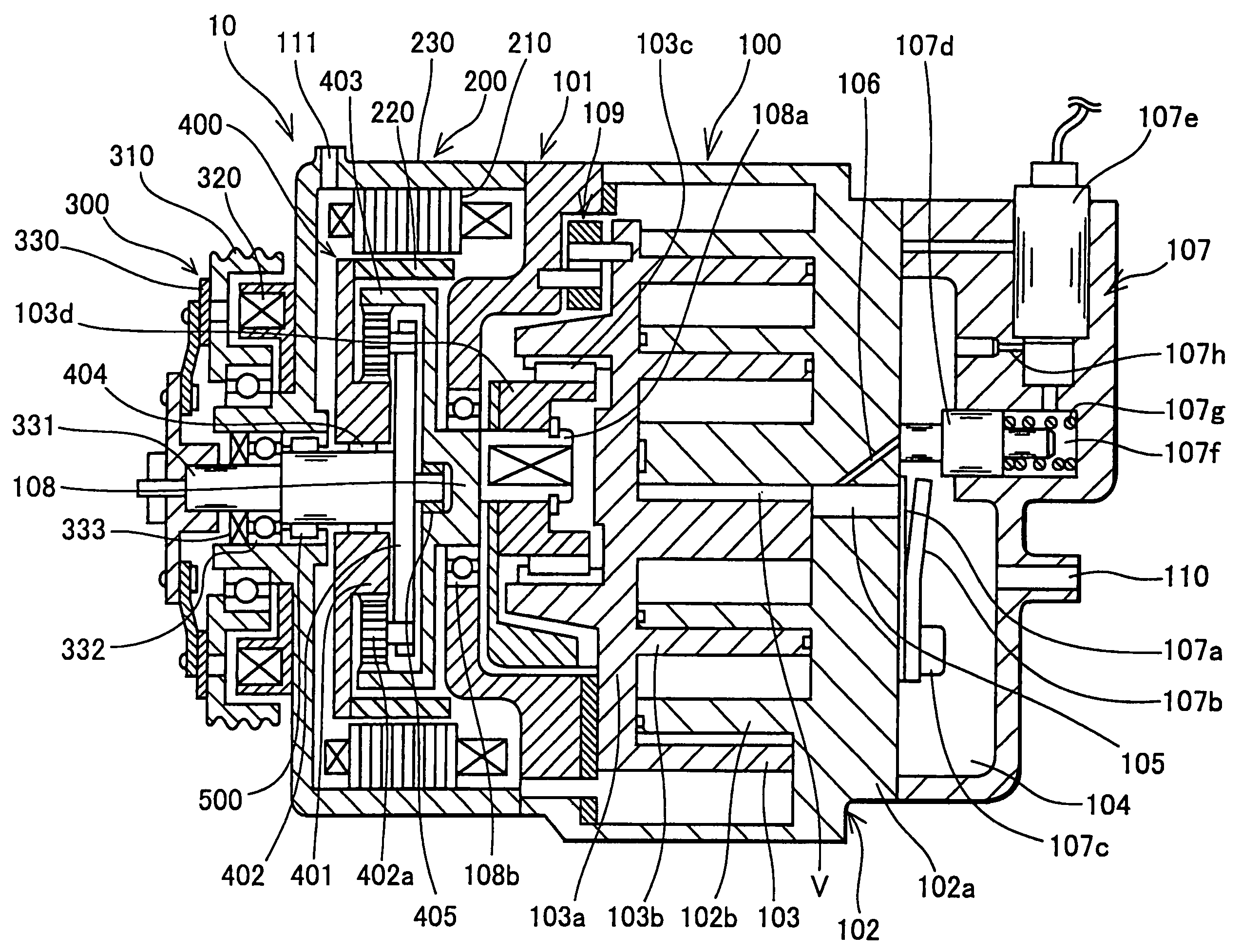
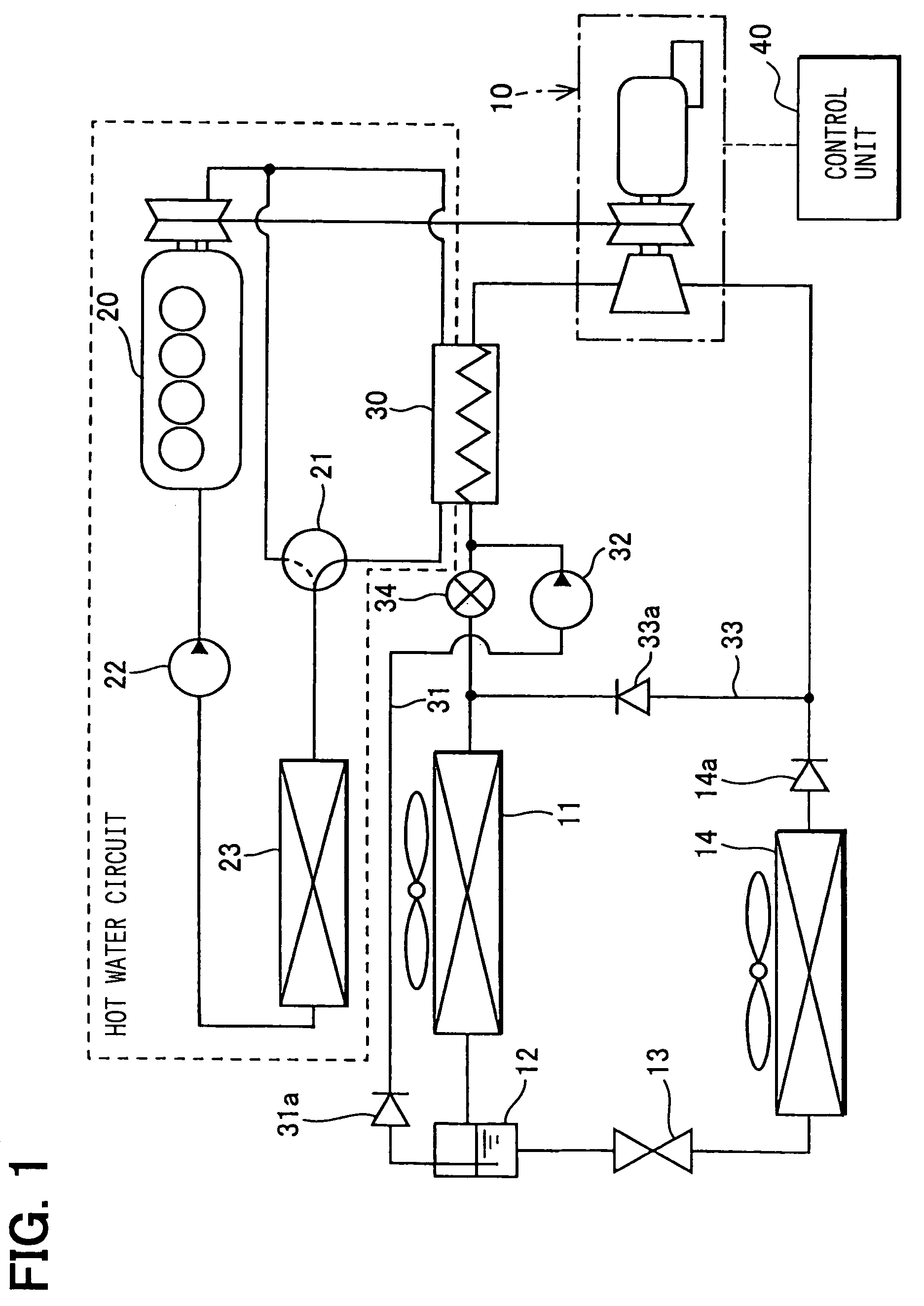
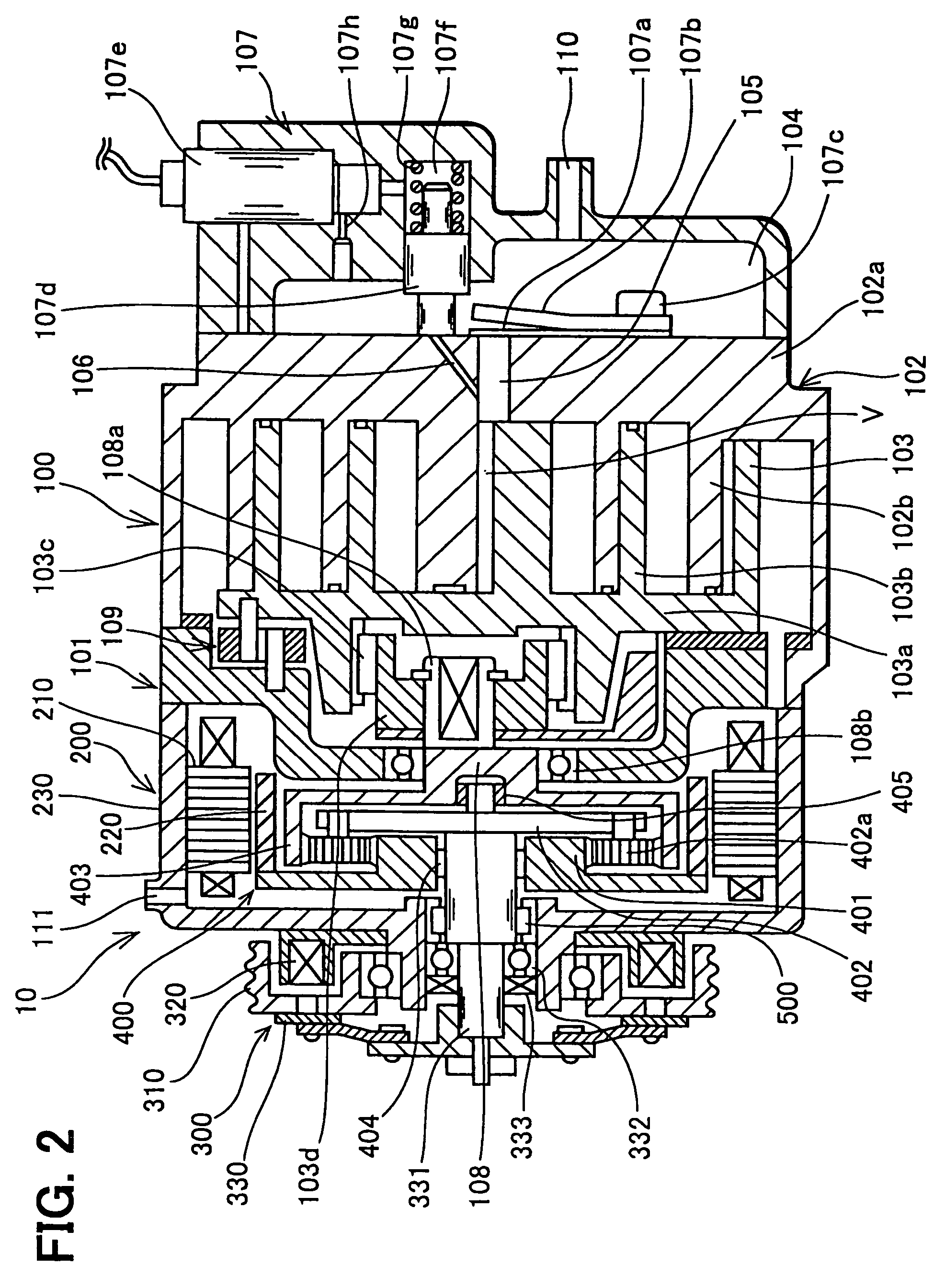
[0019]A first embodiment of the present invention will now be explained with reference to FIGS. 1 through 3. A fluid machine of the present invention is used to, for example, a motor vehicle, which is equipped with an air-conditioning system and a waste heat utilizing system. The waste heat utilizing system is composed of a Rankine cycle, which collects waste heat from an internal combustion engine generating a driving power for the motor vehicle. In addition, in the fluid machine of the present invention, the heat (heating or cooling energy) generated by the fluid machine is utilized to perform an air-conditioning operation for the motor vehicle.

[0020]In FIG. 1, a reference numeral 10 designates a fluid machine comprising an expansion-and-compressor device, so that the fluid machine operates as a compressor for compressing a gas-phase. refrigerant (this is referred to as a pump mode operation) and also as a power generator for generating a mechanical driving force by converting flu...


PUM

PropertyMeasurementUnit
pressureaaaaaaaaaa
rotational speedaaaaaaaaaa
electric energyaaaaaaaaaa

Abstract

An expansion-and-compressor device of a fluid machine has a pump mode operation in which the expansion-and-compressor device is rotated by a driving force from a driving source to compress working fluid, and a motor mode operation in which the fluid pressure is converted into energy of movement to output kinetic energy. The fluid machine further has a transmission device for transmitting the driving force from the driving source with increased rotational speed, when the expansion-and-compressor device is operated in the pump mode operation.

Description

CROSS REFERENCE TO RELATED APPLICATION[0001]This application is based on Japanese Patent Application No. 2004-59528 filed on Mar. 3, 2004, the disclosure of which is incorporated herein by reference.FIELD OF THE INVENTION[0002]The present invention relates to a fluid machine having a pump mode operation for pressurizing and discharging fluid and a motor mode operation for converting fluid pressure during fluid expansion into energy of movement and for outputting kinetic energy, wherein the fluid machine is preferably used as an expansion-and-compressor device for a waste heat collecting system having Rankine cycle for collecting heat energyBACKGROUND OF THE INVENTION[0003]In a prior art fluid machine, as disclosed, for example, in Japanese Patent No. 2540738, a compressor device for a vapor compression refrigerating system is commonly used as an expansion device, and the compressor device is used as the expansion device when energy is collected by Rankine cycle.[0004]In the above fl...

Claims


Application Information

Patent Timeline
Patent Type & Authority Patents(United States)
IPC IPC(8): F25B9/06F02G5/00B60H1/32F01C1/02F01B31/00F01C13/00F01D1/00F01K19/00F01K25/10F01K27/00F04B9/14F04B17/00F04B35/00F04C18/02F04C23/02F04C25/00F04C29/00F25B1/04F25B27/00F25B27/02F25B31/00F25D9/00
CPCF01C13/00F01K25/10F01K27/00F04C29/0085F25B1/04F25B27/02F04C18/0215F04C2240/45F25B2400/14
Inventor IWANAMI, SHIGEKIASA, HIRONORIUNO, KEIICHITAKEUCHI, YASUHIROOGAWA, HIROSHI
Owner DENSO CORP
Features
  • R&D
  • Intellectual Property
  • Life Sciences
  • Materials
  • Tech Scout
  • Unparalleled Data Quality
  • Higher Quality Content
  • 60% Fewer Hallucinations
Learn More