
Encoding device decoding device

a technology of decoding device and encoder, which is applied in the direction of electrical transducers, volume compression/expansion, instruments, etc., can solve the problem of difficult to transmit information in the higher frequency band at a low transfer rate, and achieve the effect of more fidelity

Active Publication Date: 2007-10-16
PANASONIC CORP
View PDF29 Cites 83 Cited by
  • Summary
  • Abstract
  • Description
  • Claims
  • Application Information

AI Technical Summary

Benefits of technology

[0019]Accordingly to the encoding device of the present invention, the spectral data in the higher frequency band is not quantized and encoded as it is, but the sub information representing the characteristics of the spectral data in the higher frequency band by the fewer parameters than that of the lower frequency band is encoded. Therefore, there is an effect that the spectral data in the higher frequency band can be encoded with a very little amount of data, compared with that in the lower frequency band. Also, according to the conventional MPEG-2 AAC, the audio signals all over the bandwidth are encoded by the same method, so it is difficult to transmit the information in the higher frequency band at a low transfer rate. However, according to the encoding device of the present invention, the information in the higher frequency band can be transmitted without substantially increasing the amount of information after encoding, so there is an effect that the decoding device of the present invention can decode the audio signal to reproduce higher-quality sound in the higher frequency band than the conventional decoding device.
[0022]According to the encoding device of the present invention, the quantized value of the spectral data which is a normalizing factor or a peak, each of which is one parameter for each group (scale factor band) in the higher frequency band, is generated as the sub information, so the data amount of the sub information is very little even if a certain number of bits, 8 bits, for instance, is assigned to represent one normalizing factor or quantized value. Therefore, the maximum amplitude of the spectral data for each group in the higher frequency band can be roughly represented with a small amount of data. As a result, according to the encoding device of the present invention, the information for generating the audio signals in the higher frequency band to reproduce the original sound can be transmitted with only a very little more transmission amount than the conventional one, even via a transmission channel at a low transmission rate. That is, there is an effect that the decoding device of the present invention can reconstruct the audio signals to reproduce the original sound with more fidelity.
[0025]According to the encoding device of the present invention, a rough spectral shape in each group (scale factor band) in the higher frequency band can be represented with a little amount of data by the frequency position of the peak spectral data or the positive or negative sign of the spectral data at a predetermined frequency position in the higher frequency band. Therefore, there is an effect that the copied spectral data can be corrected so as to be approximate to the spectral data in the higher frequency band with accuracy.
[0027]According to the encoding device of the present invention, when there is in the lower frequency band a spectrum of a shape closely similar to that of the spectrum in the higher frequency band, the spectrum in the lower frequency band may be specified and copied to the higher frequency band. Therefore, there is an effect that the spectrum in the higher frequency band can be represented with more fidelity, with a very small amount of data.

Problems solved by technology

Also, according to the conventional MPEG-2 AAC, the audio signals all over the bandwidth are encoded by the same method, so it is difficult to transmit the information in the higher frequency band at a low transfer rate.

Method used


Image

  • Encoding device decoding device
  • Encoding device decoding device
  • Encoding device decoding device

Examples


Embodiment Construction

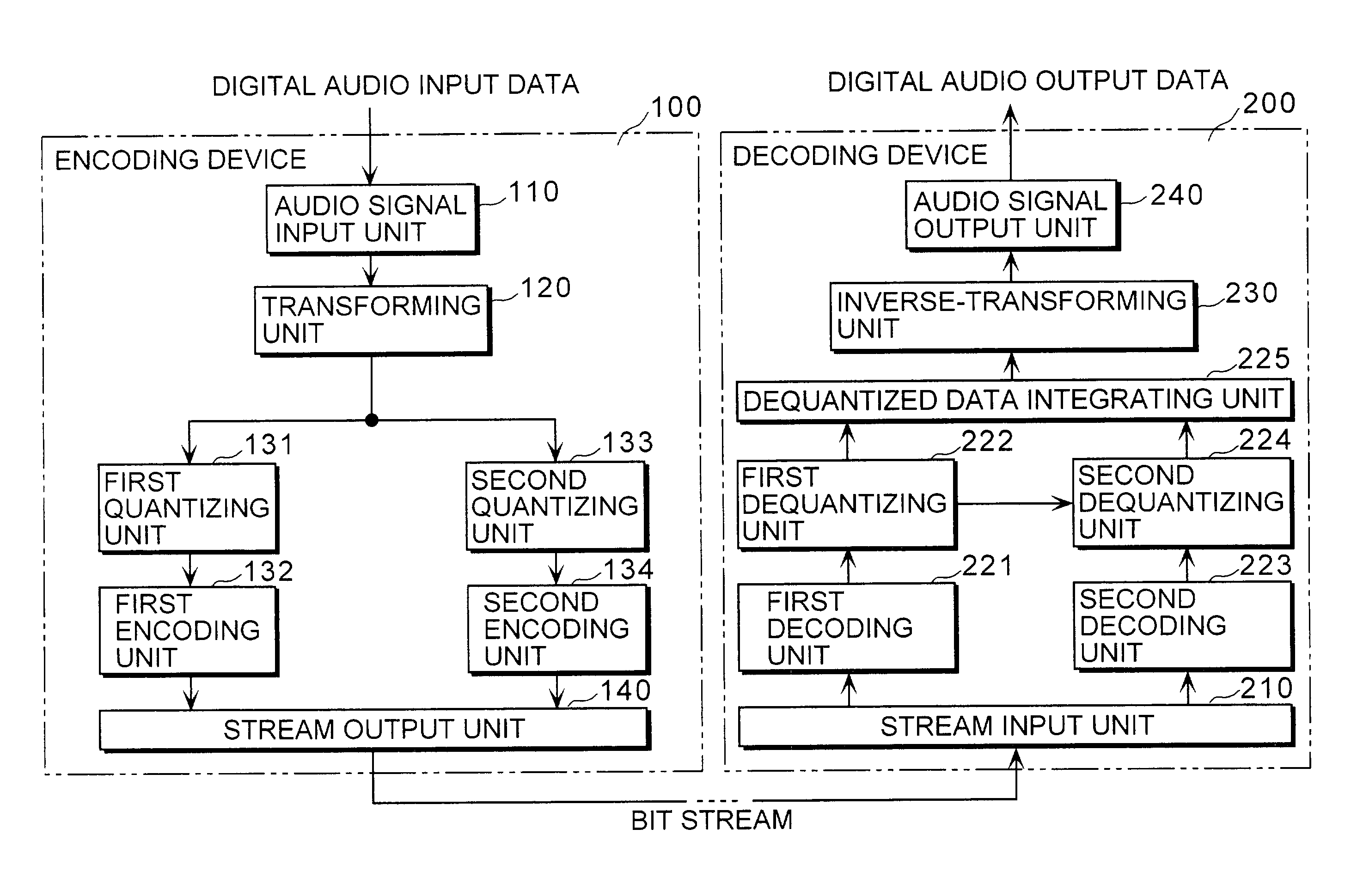
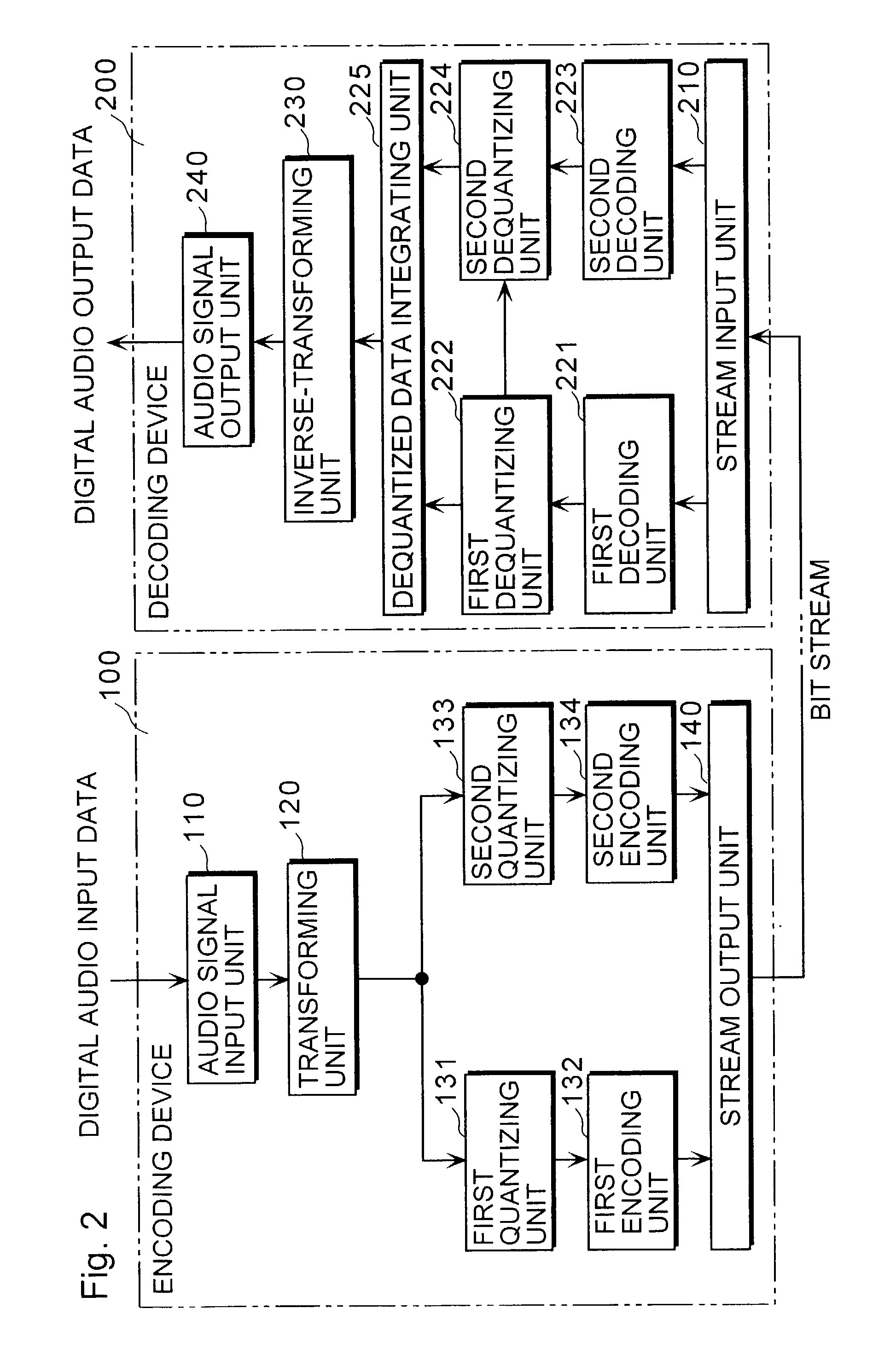
[0052]The encoding device 100 and the decoding device 200 according to an embodiment of the present invention will be explained in detail below, with reference to the figures. Also, the present embodiment will be explained by taking MPEG-2 AAC as an example. FIG. 2 is a block diagram showing the configuration of the encoding device 100 and the decoding device 200 according to the embodiment of the present invention.

(Encoding Device 100)

[0053]The encoding device 100, when receiving an audio signal, compresses and encodes the audio signal in the lower frequency band according to MPEG-2 AAC. In addition, it generates sub information indicating characteristics of the audio signal in the higher frequency band, compresses and encodes it, integrates it into the encoded bit stream in the lower frequency band, and outputs it. The encoding device 100 includes an audio signal input unit 110, a transforming unit 120, a first quantizing unit 131, a first encoding unit 132, a second quantizing un...


PUM


Abstract

An encoding device (100) includes (i) a first encoding unit (132) that encodes spectral data in the lower frequency band represented by a plularity of parameters, out of the spectral data obtained by transforming an audio signal inputted for a fixed time length, (ii) a second quantizing unit (133) that generates sub information representing characteristics of the spectral data in the higher frequency by fewer parameters than those for the lower frequency band, out of the spectral data obtained by the transformation, (iii) a second encoding unit (134) that encodes the generated sub information, and (iv) a stream output unit (140) that outputs the data encoded by the first encoding unit (132) and the data encoded by the second encoding unit (134).

Description

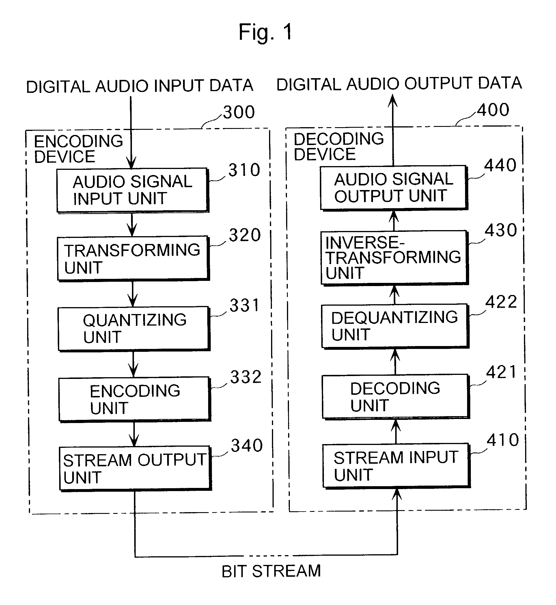
TECHNICAL FIELD[0001]The present invention relates to technology for encoding and decoding digital audio data to reproduce high-quality sound.BACKGROUND ART[0002]In recent years, a variety of audio compression methods have been developed. MPEG-2 Advanced Audio Coding (AAC) is one of such compression methods, and is defined in detail in “ISO / IEC 13818-7 (MPEG-2 Advanced Audio Coding, AAC)”.[0003]First, the conventional encoding and decoding procedures will be described below using FIG. 1. FIG. 1 is a block diagram showing a configuration of an encoding device 300 and a decoding device 400 according to the conventional MPEG-2 AAC method. The encoding device 300 is a device that compresses and encodes an inputted audio signal based on MPEG-2 AAC, and includes an audio signal input unit 310, a transforming unit 320, a quantizing unit 331, an encoding unit 332 and a stream output unit 340.[0004]The audio signal input unit 310 divides digital audio data that is an input signal into every ...

Claims


Application Information

Patent Timeline
IPC IPC(8): G10L19/00G10L19/02G10L21/038
CPCG10L21/038G10L19/0208
Inventor NISHIO, KOSUKETSUSHIMA, MINEOTANAKA, NAOYANORIMATSU, TAKESHI
Owner PANASONIC CORP
Learn More