Check patentability & draft patents in minutes with Patsnap Eureka AI!

Optical sensor

Active Publication Date: 2007-10-23
HAMAMATSU PHOTONICS KK
View PDF12 Cites 13 Cited by
  • Summary
  • Abstract
  • Description
  • Claims
  • Application Information

AI Technical Summary

Benefits of technology

[0011]Furthermore, when the brightness differs greatly, depending on the positioning of an object, and when the light detection apparatus (a solid-state image pickup apparatus) described in the above reference is employed to image, at high sensitivity, a darker portion of an object, saturation of an output signal for the brighter portion of the object will occur. Whereas, when the brighter portion of an object is to be imaged to avoid the occurrence of saturation, the imaging sensitivity for the darker portion of the object is reduced.
[0013]To resolve these problems, it is an objective of the present invention to provide a light detection apparatus that can rapidly detect the intensity of incident light.
[0030]Furthermore, according to the light detection apparatus of the present invention, (1) the capacitance of the integrating capacitor unit can be set to a first capacitance or a second capacitance, and the first capacitance is 2n times (n is an integer equal to or greater than one) the second capacitance, and (2) the A / D converter circuit outputs a digital signal having n or greater bits. In this case, the digital signal output by the A / D converter circuit is subject to n-bit left shift, as needed, and the value of the obtained digital signal represents a superior linearity relative to the intensity of incident light.

Problems solved by technology

Thus, the light detection apparatus can not rapidly detect the intensity of incident light.
As is described above, for the light detection apparatus (solid-state image pickup apparatus) in the above reference, the capacitance of the integrating capacitor unit is appropriately set for each imaging in order to extend the dynamic range for the detection of the intensity of the incident light; however, on a screen, the dynamic range for detecting the intensity of the incident light for each pixel can not be increased.

Method used


Image

  • Optical sensor
  • Optical sensor
  • Optical sensor

Examples


Embodiment Construction

[0043]The embodiments of the present invention will now be described in detail while referring to the accompanying drawings. For the explanation of the drawings, the same reference numerals are employed to denote corresponding components to avoid overlapping during the explanation.

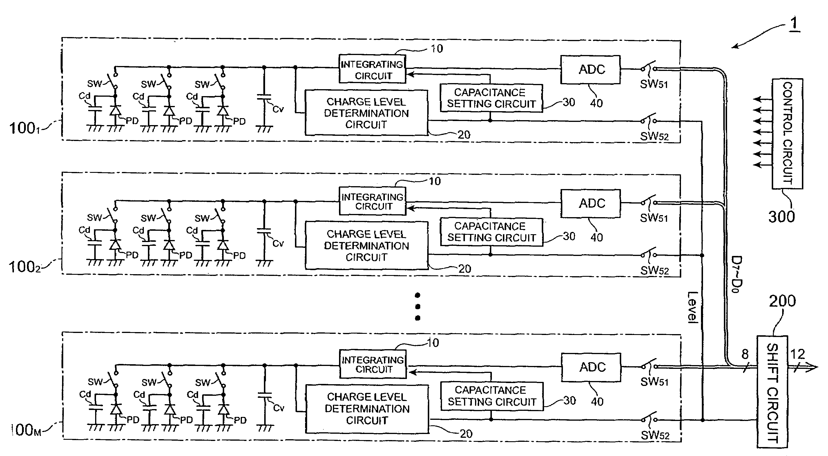
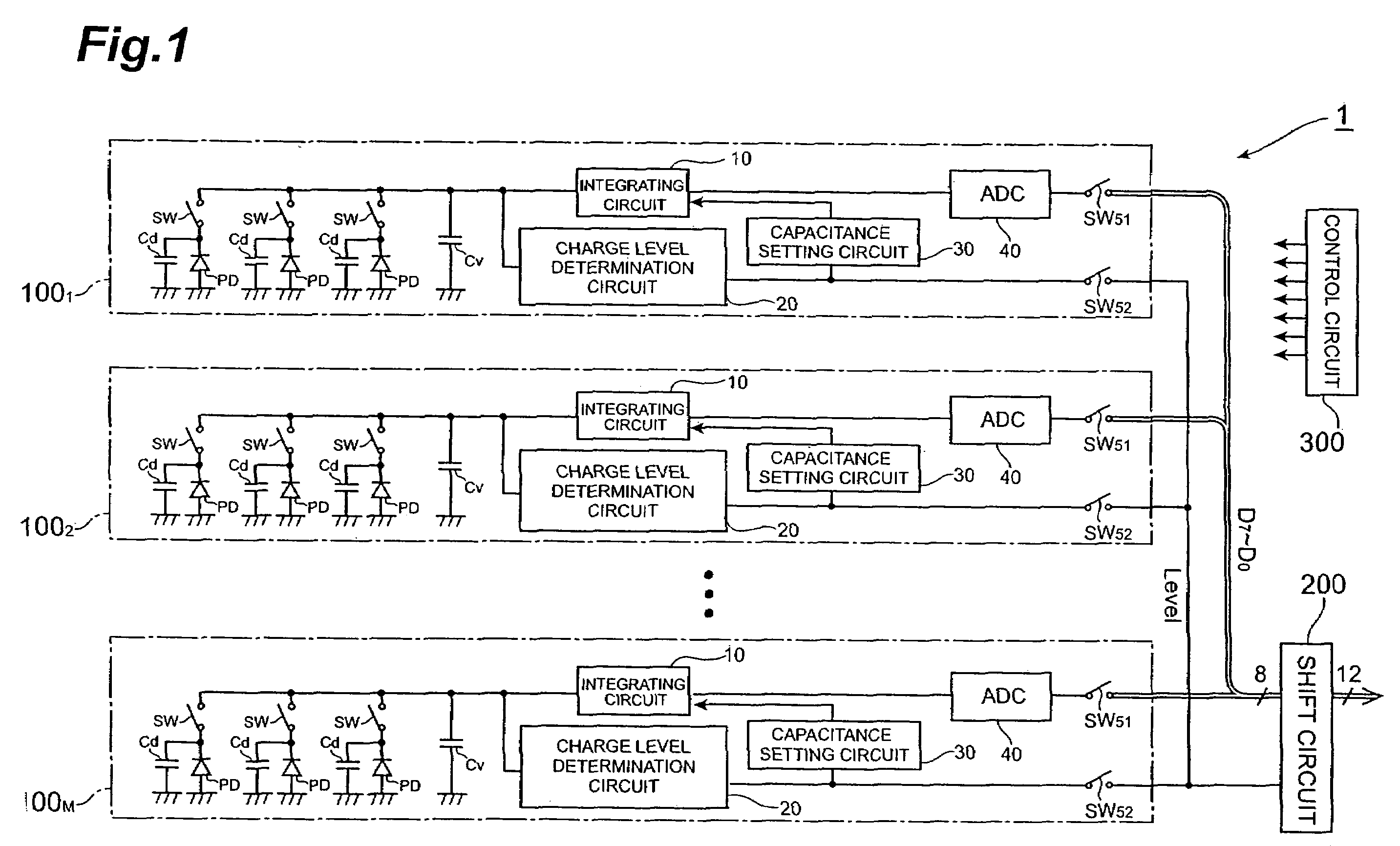
[0044]FIG. 1 is a schematic diagram showing the configuration of a light detection apparatus 1 according to the present embodiment. This light detection apparatus 1 includes: M units (M is an integer equal to or greater than two) 1001 to 100M, a shift circuit 200 and a control circuit 300. These M units 1001 to 100M have the same configuration to one another, and each includes a plurality of photodiodes (light detection devices) PD, switches SW, an integrating circuit 10, a charge level determination circuit 20, a capacitance setting circuit 30, an A / D converter circuit 40 and switches SW51 and SW52.

[0045]For the photodiodes PD of each unit 100m (m is an arbitrary integer equal to or greater than one and e...


PUM


Abstract

An amount of charges consonant with the intensity of the light entering photodiodes is generated, and the level of the charges is determined by a charge level determination circuit. Based on this determined charge level, a capacitance setting circuit sets a capacitance of an integrating capacitor unit in an integrating circuit. Thereafter, in the integrating circuit, the charges generated by the photodiodes are integrated in the integrating capacitor unit, and a voltage having a value consonant with the amount of the integrated charges is output. When background light is strong and the overall intensity of incident light is high, a comparatively large capacitance is set for the variable capacitor unit of the integrating circuit, and the intensity of the incident light is detected without saturation. When background light is weak and the overall intensity of incident light is low, a comparatively small capacitance is set for the variable capacitor unit of the integrating circuit, and the intensity of the incident light is detected at high sensitivity, regardless of the surrounding conditions.

Description

TECHNICAL FIELD[0001]The present invention relates to a light detection apparatus for outputting a digital signal having a value consonant with the intensity of incident light.BACKGROUND ART[0002]A light detection apparatus includes one or more light detection devices and an integrating circuit for outputting a voltage having a value consonant with the amount of electrical charges output by the light detection devices. In this light detection apparatus, electrical charges output by the light detection devices, in amounts equivalent to the intensity of the incident light, are integrated in the integrating circuit and are output by the integrating circuit as a voltage having a value consonant with the amount of the integrated charges, and based on this voltage, the intensity of the incident light is obtained.[0003]The light detection apparatus may further include an A / D converter circuit for converting into a digital signal a voltage (analog signal) output by the integrating circuit. ...

Claims


Application Information

Patent Timeline
IPC IPC(8): H04N3/14G01J1/46H04N5/335
CPCG01J1/46
Inventor MIZUNO, SEIICHIROYAMAMOTO, HIROOFUJITA, KAZUKI
Owner HAMAMATSU PHOTONICS KK
Features
  • R&D
  • Intellectual Property
  • Life Sciences
  • Materials
  • Tech Scout
  • Unparalleled Data Quality
  • Higher Quality Content
  • 60% Fewer Hallucinations
Learn More