Protective device with tamper resistant shutters

Inactive Publication Date: 2007-12-25
PASS SEYMOUR
View PDF36 Cites 78 Cited by
  • Summary
  • Abstract
  • Description
  • Claims
  • Application Information

AI Technical Summary

Benefits of technology

[0011]The present invention addresses the needs described above. The present invention provides an integrated protective device that includes mis-wire condition detector that operates in conjunction with a protective shutter. The shutter prevents insertion of a plug into the receptacle until such time as power has been properly connected to the line terminals of

Problems solved by technology

Fault conditions include those that result in risk electrocution of personnel, or fire.
There are several safety issues that heretofore have not been addressed in an integrated way.
The first type of problem are fault conditions such as ground faults and arc faults that may result in electrocution or fire, respectively.
The second type of problem involves the inadvertent insertion of objects, such as paper clips and screwdriver blades into the receptacle contact openings.
This situation also involves an electric shock hazard.
A third type of problem relates to the introduction of contaminants into the device during shipping, handling, or storage, or following installation.
Any of these contaminants may result in the failure of the protective device.
With respect to the first problem, historical problems with these devices include the possibility of the line wires being connected to the load terminals during installation, also known as miswiring.
Historical problems include a defective solenoid d

Method used


Image

  • Protective device with tamper resistant shutters
  • Protective device with tamper resistant shutters
  • Protective device with tamper resistant shutters

Examples


Embodiment Construction

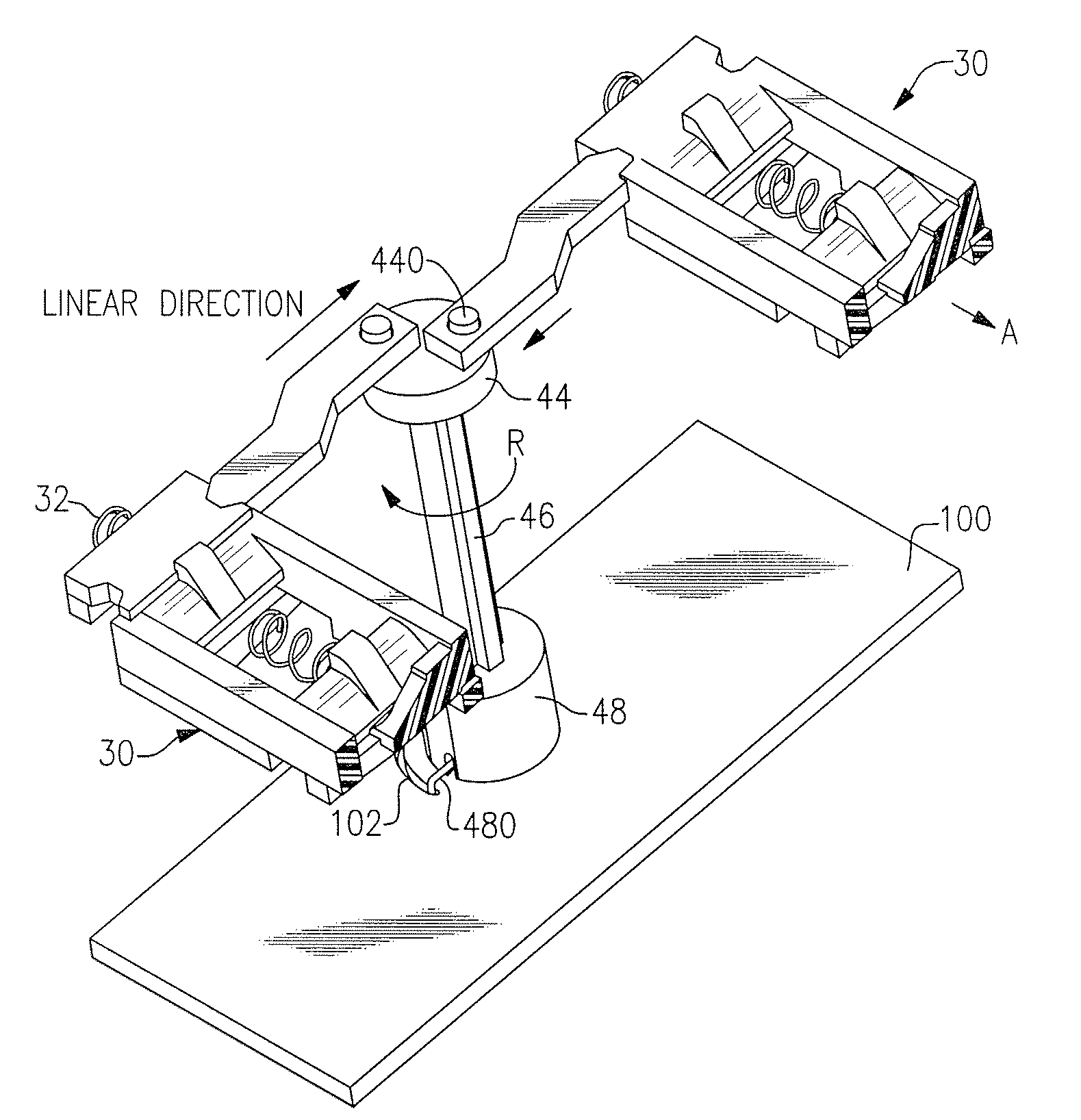
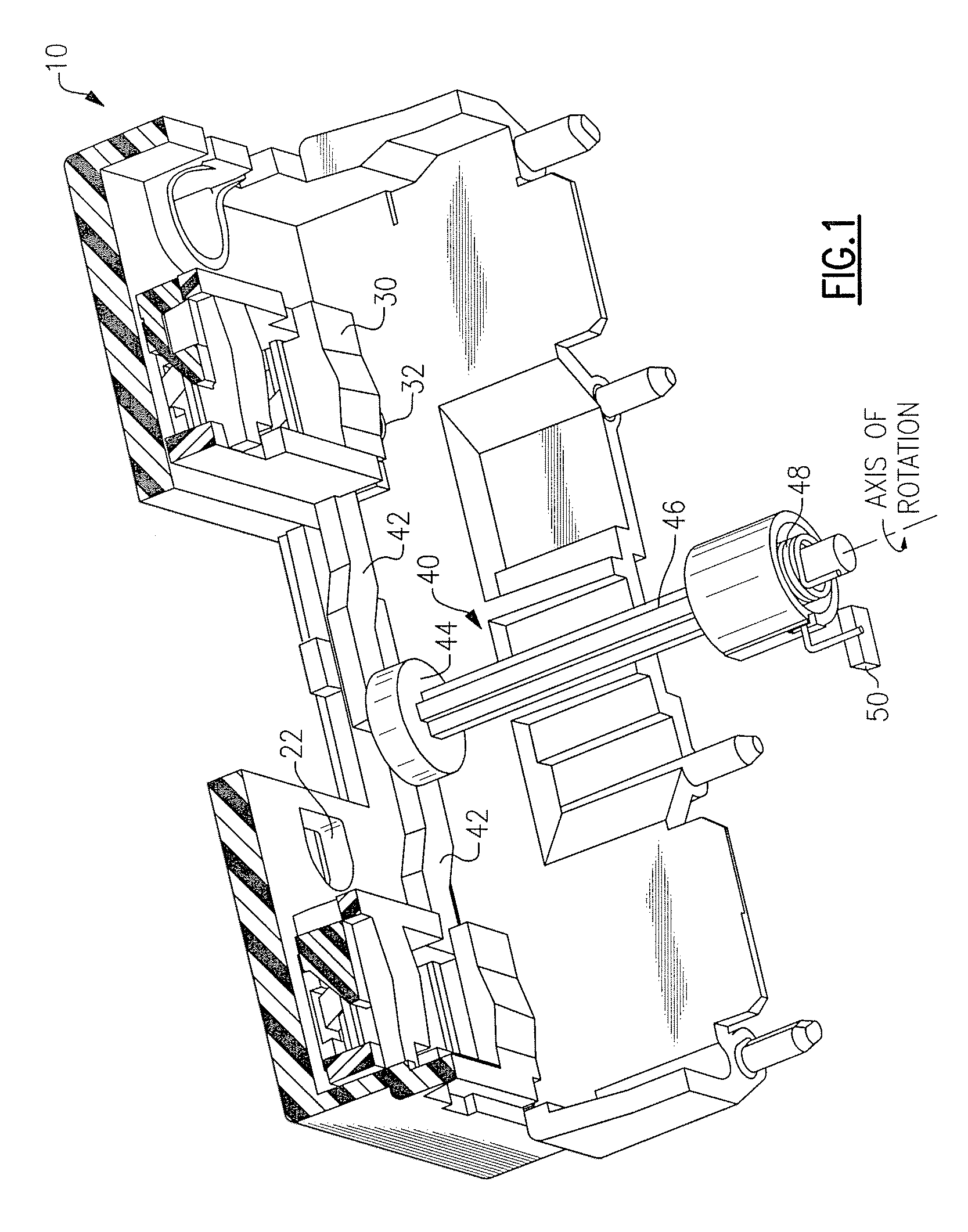
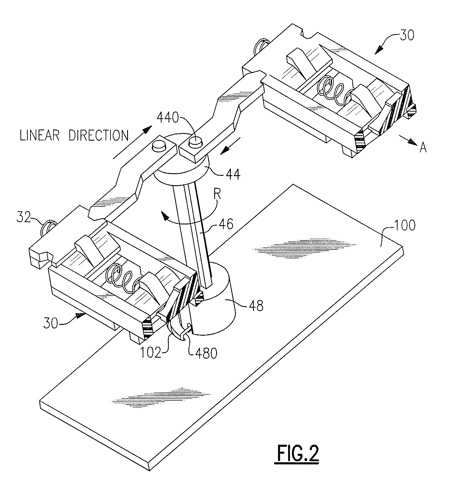
[0027]Reference will now be made in detail to the present exemplary embodiments of the invention, examples of which are illustrated in the accompanying drawings. Wherever possible, the same reference numbers will be used throughout the drawings to refer to the same or like parts. An exemplary embodiment of the shuttered protective device of the present invention is shown in FIG. 1, and is designated generally throughout by reference numeral 10.

[0028]In accordance with the invention, the present invention is directed to a protection device that includes line terminals coupled to a power source disposed in an electric power distribution system. The protection device is configured to protect a portion of the power distribution system from at least one fault condition. The device includes a receptacle member that includes a housing and a cover. The cover includes receptacle openings configured to accommodate plug contact blades. Receptacle contacts are disposed in the housing. The recep...


PUM


Abstract

The present invention is directed to a protection device that includes line terminals coupled to a power source disposed in an electric power distribution system. The protection device is configured to protect a portion of the power distribution system from at least one fault condition. The device includes a receptacle member that has includes a housing and a cover. The cover includes receptacle openings configured to accommodate plug contact blades. Receptacle contacts are disposed in the housing. The receptacle contacts are also coupled to the line terminals to thereby establish an electrical connection between the receptacle contacts and the line terminals. Each receptacle contact is in communication with a corresponding receptacle opening. A protective shutter mechanism is integrated into the housing. The protective shutter mechanism is movable from a closed position to an open position upon insertion of the plug contact blades. The protective shutter mechanism is substantially hermetically sealed in the closed position. The protective shutter mechanism is also not movable from the closed position to the open position upon insertion of an object into only one receptacle opening, such that the object is prevented from making contact with the corresponding receptacle contact.

Description

BACKGROUND OF THE INVENTION[0001]1. Field of the Invention[0002]The present invention relates generally to electrical protection devices, and particularly to electrical protection devices with safety features.[0003]2. Technical Background[0004]Ground fault circuit interrupters (GFCIs), and arc fault circuit interrupters (AFCIs) are examples of protective devices in electric circuits. These devices may be disposed in a receptacle that is subsequently installed in a wall box. The receptacle has line terminals for connection to the power line, and load terminals for connection to a load. The load terminals include receptacle contacts and feed-thru terminals. The receptacle contacts are configured to accommodate the blades of a plug connector, which are inserted to provide power to a load. Feed-thru terminals, on the other hand, are configured to accommodate wires which are connected to one or more additional receptacles, known as a downstream receptacles. The downstream receptacle may ...

Claims


Application Information

Patent Timeline
IPC IPC(8): H02H3/16H01H73/00
CPCH01R13/641H01R13/4534
Inventor RADOSAVLJEVIC, DEJANWEEKS, RICHARD
Owner PASS SEYMOUR
Why Eureka
Try Eureka