Check patentability & draft patents in minutes with Patsnap Eureka AI!

Redundant control circuit for hot melt adhesive assembly heater circuits and temperature sensors

a technology of hot melt adhesive and control circuit, which is applied in the direction of process and machine control, process control, instruments, etc., can solve the problems of general failure, mechanical failure due to wear, electrical failure,

Active Publication Date: 2008-02-19
ILLINOIS TOOL WORKS INC
View PDF8 Cites 4 Cited by
  • Summary
  • Abstract
  • Description
  • Claims
  • Application Information

AI Technical Summary

Benefits of technology

This solution prevents extended downtime by allowing the production line to continue operating even when a failure occurs, as the redundant components can take over, delaying the need for replacement until scheduled maintenance, thus minimizing production losses.

Problems solved by technology

In connection with hot melt adhesive dispensing systems, failures can generally occur within two different categories, that is, mechanical failures due to wear, or electrical failures due to electrical malfunctions.
In either case, that is, whether a failure is experienced in connection with the heater circuit, or in connection with the temperature sensor, such failures typically cause the hot melt adhesive dispensing production line to be shut down for extended periods of time, in order to implement the repair or replacement of the failed components, whereby valuable production time is lost.

Method used


Image

  • Redundant control circuit for hot melt adhesive assembly heater circuits and temperature sensors
  • Redundant control circuit for hot melt adhesive assembly heater circuits and temperature sensors

Examples


Embodiment Construction

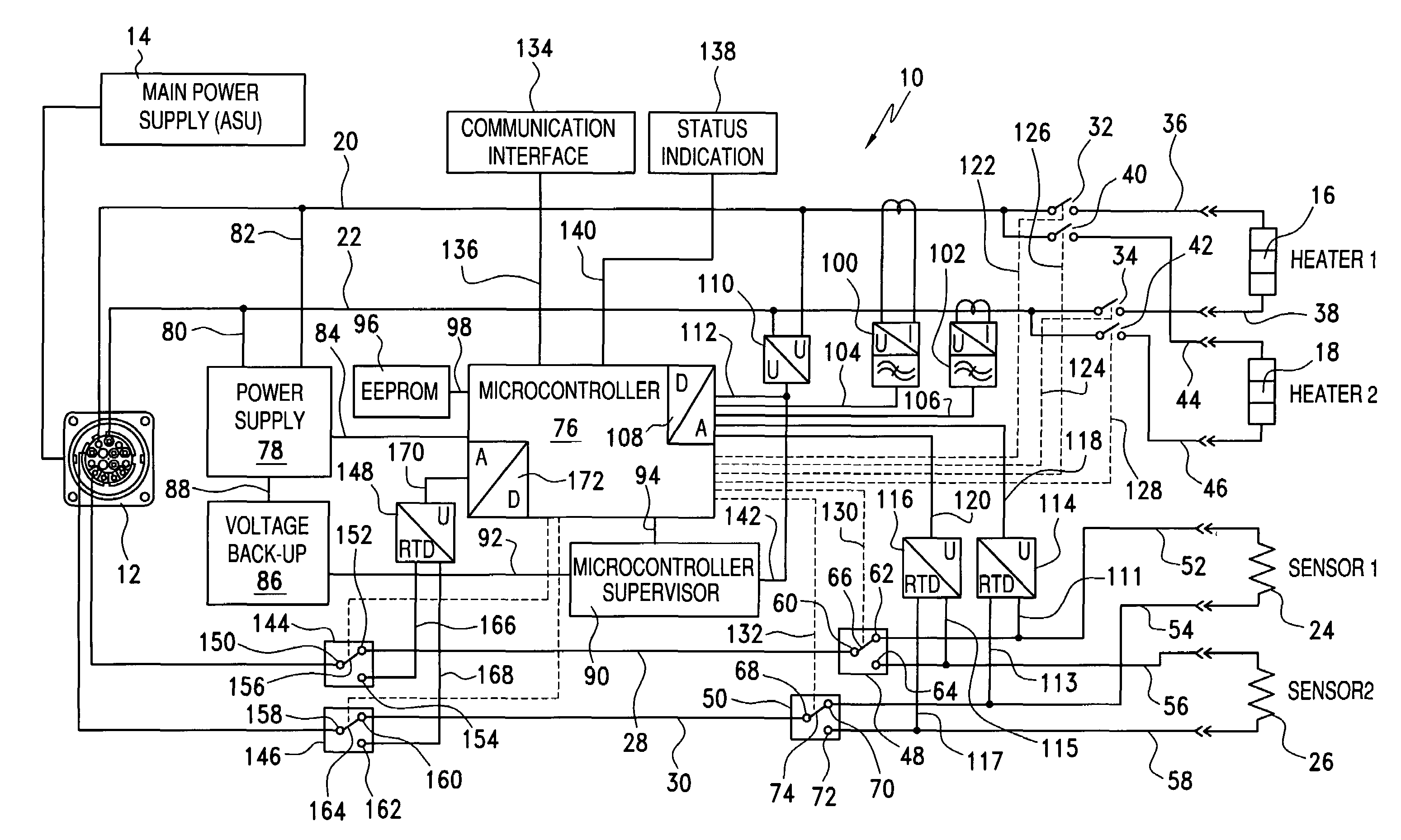
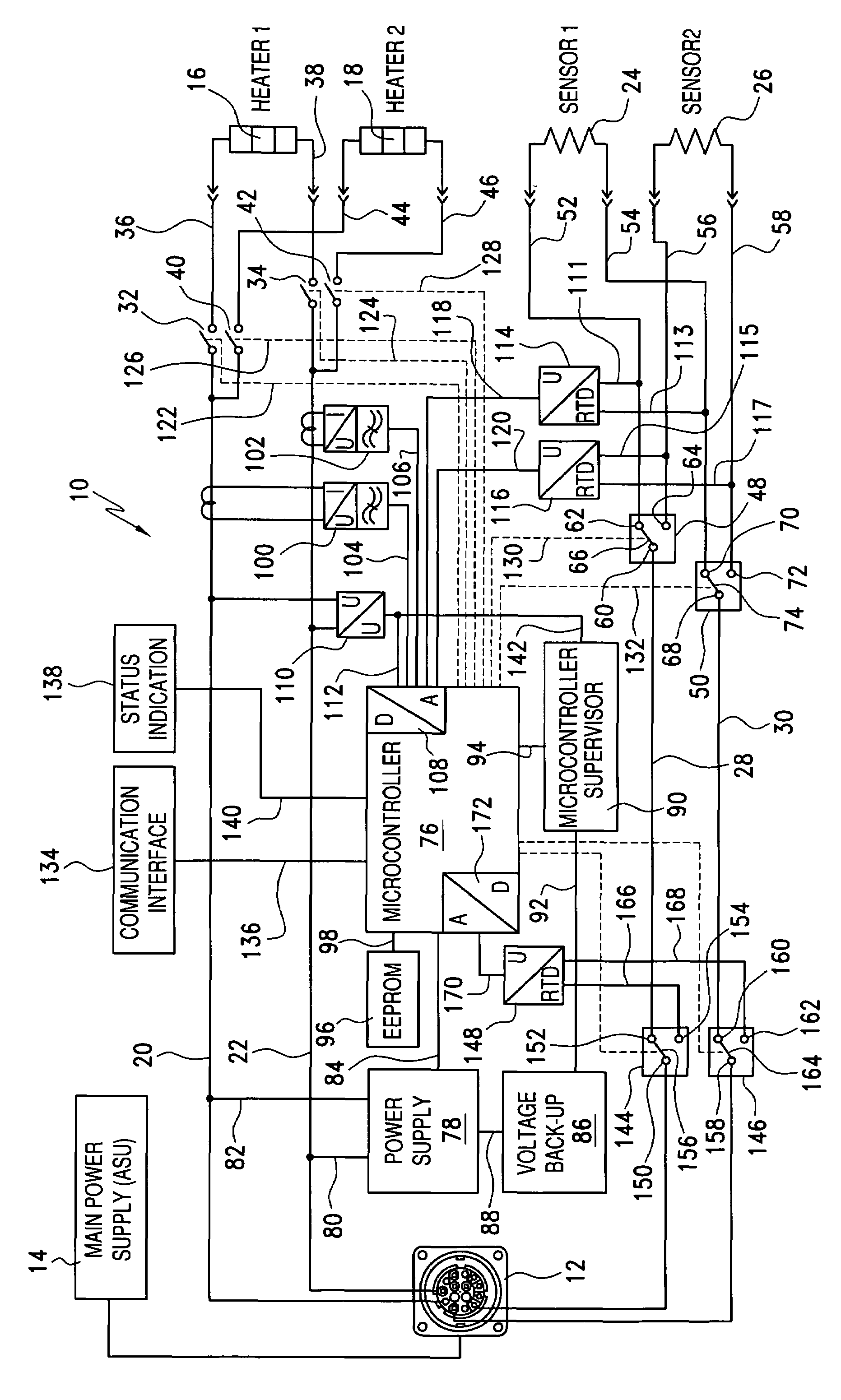
[0008]Referring now to the drawings, and more particularly to the SOLE FIGURE thereof, the new and improved redundant control circuit, which has been developed in accordance with the principles and teachings of the present invention and which shows the cooperative parts thereof, and which is adapted to be operatively associated with a hot melt adhesive hose assembly, such as, for example, that disclosed within the aforenoted copending United States Patent Application entitled HOT MELT ADHESIVE HOSE ASSEMBLY HAVING REDUNDANT COMPONENTS, which was filed on May 6, 2005, and which has been assigned Ser. No. 11 / 123,053, is disclosed and is generally indicated by the reference character 10. As is well known in the hot melt adhesive material dispensing art, hot melt adhesive material is normally supplied to a hot melt adhesive hose assembly, not shown, from a hot melt adhesive supply unit, also not shown, in a heated state, and a heater circuit or heater assembly is conventionally operativ...


PUM


Abstract

A redundant control circuit comprises a pair of heater circuits for heating a hot melt adhesive hose assembly to a predetermined temperature level, and a pair of temperature sensors which are used to sense the temperature of the hot melt adhesive hose assembly and to control energization of the heater circuits in order to maintain the desired temperature level. A first one of the heater circuits would initially be electrically connected to the hot melt adhesive hose assembly electrical circuitry, and in a similar manner, a first one of the temperature sensors would likewise be electrically connected to the hot melt adhesive hose assembly electrical circuitry. Subsequently, should a failure occur within the first one of the heater circuits, then an electrical switch mechanism would be activated so as to effectively remove the first, failed heater circuit from the hot melt adhesive hose assembly electrical circuitry, and substantially simultaneously, electrically connect the second one of the heater circuits to the hot melt adhesive hose assembly electrical circuitry. Similar switching procedures would also be implemented in connection with the pair of temperature sensors should a failure occur within a first one of the temperature sensors initially incorporated within the hot melt adhesive hose assembly electrical circuitry.

Description

CROSS REFERENCE TO RELATED PATENT APPLICATIONS[0001]This patent application is related to copending United States Patent Application entitled HOT MELT ADHESIVE HOSE ASSEMBLY HAVING REDUNDANT COMPONENTS, which was filed on May 6, 2005, and which has been assigned Ser. No. 11 / 123,053.FIELD OF THE INVENTION[0002]The present invention relates generally to hot melt adhesive dispensing systems, and more particularly to a new and improved redundant control circuit which effectively has redundant components inherently incorporated therein, such as, for example, redundant hot melt adhesive heater circuits, and redundant hot melt adhesive temperature sensors, whereby should a failure occur within one of the hot melt adhesive heater circuits, or within one of the hot melt adhesive temperature sensors, switch mechanisms may be suitably actuated so as to effectively withdraw the failed hot melt adhesive heater circuit, or the failed hot melt adhesive temperature sensor, from its operative or fun...

Claims


Application Information

Patent Timeline
Patent Type & Authority Patents(United States)
IPC IPC(8): H05B1/02B67D7/08B67D7/80
CPCB05C5/001B05C11/1042G05B19/048G05D23/1928G05D23/19B05C5/00
Inventor BOURGET, DANIEL D.HEERDT, DIETER B.
Owner ILLINOIS TOOL WORKS INC
Features
  • R&D
  • Intellectual Property
  • Life Sciences
  • Materials
  • Tech Scout
  • Unparalleled Data Quality
  • Higher Quality Content
  • 60% Fewer Hallucinations
Learn More