Supercharge Your Innovation With Domain-Expert AI Agents!

Head support mechanism, head arm assembly, and disk drive apparatus with head arm assembly with weight formed around horizontal bearing

a technology of head arm and disk drive, which is applied in the direction of maintaining head carrier alignment, recording information storage, instruments, etc., can solve the problems of low shock resistance, high risk of excessive shock force, and low shock resistance, and achieve excellent shock resistance and prevent an increase in inertia moment

Inactive Publication Date: 2008-04-29
TDK CORPARATION
View PDF6 Cites 2 Cited by
  • Summary
  • Abstract
  • Description
  • Claims
  • Application Information

AI Technical Summary

Benefits of technology

This configuration enhances shock resistance, reduces inertia moment, and allows for easier weight optimization, enabling the use of lighter materials like molded resin to improve bending rigidity and facilitate stacking of multiple head arm assemblies.

Problems solved by technology

However, the cantilever structure has a serious problem of a low shock resistance.
However, in a magnetic disk drive for 2.5-inch disks, which is mounted in a notebook computer, an excessive shock force is likely to be applied.
Accordingly, the low shock resistance is a serious problem.
However, in a larger-diameter magnetic disk drive for, for example, 1.8-inch or 2.5-inch disks, the arm is longer, so that it is difficult to ensure a sufficient shock resistance.
Moreover, since the VCM is used to balance the balance structure, the magnetic disk apparatus cannot be configured so as to allow a plurality of HAAs with the balance structure to stack each other.
Thus, any increase in the magnitude of displacement in this trailing end section is undesirable.
Furthermore, because the extended trailing end section 11a of the load beam 11 or the weight attached to the trailing end section is at a substantial distance from the horizontal axis of rotation (the center of seek rotation), disadvantageously, an inertia moment during a seek operation may directly increase.
In addition, since the weight is provided in a gap between the support arm and the magnetic disk, it is difficult to optimize the shape of the weight.
Namely, it is quite difficult to make a weight shape suitable for bending characteristics or torsion and sway characteristics.

Method used


Image

  • Head support mechanism, head arm assembly, and disk drive apparatus with head arm assembly with weight formed around horizontal bearing
  • Head support mechanism, head arm assembly, and disk drive apparatus with head arm assembly with weight formed around horizontal bearing
  • Head support mechanism, head arm assembly, and disk drive apparatus with head arm assembly with weight formed around horizontal bearing

Examples


Embodiment Construction

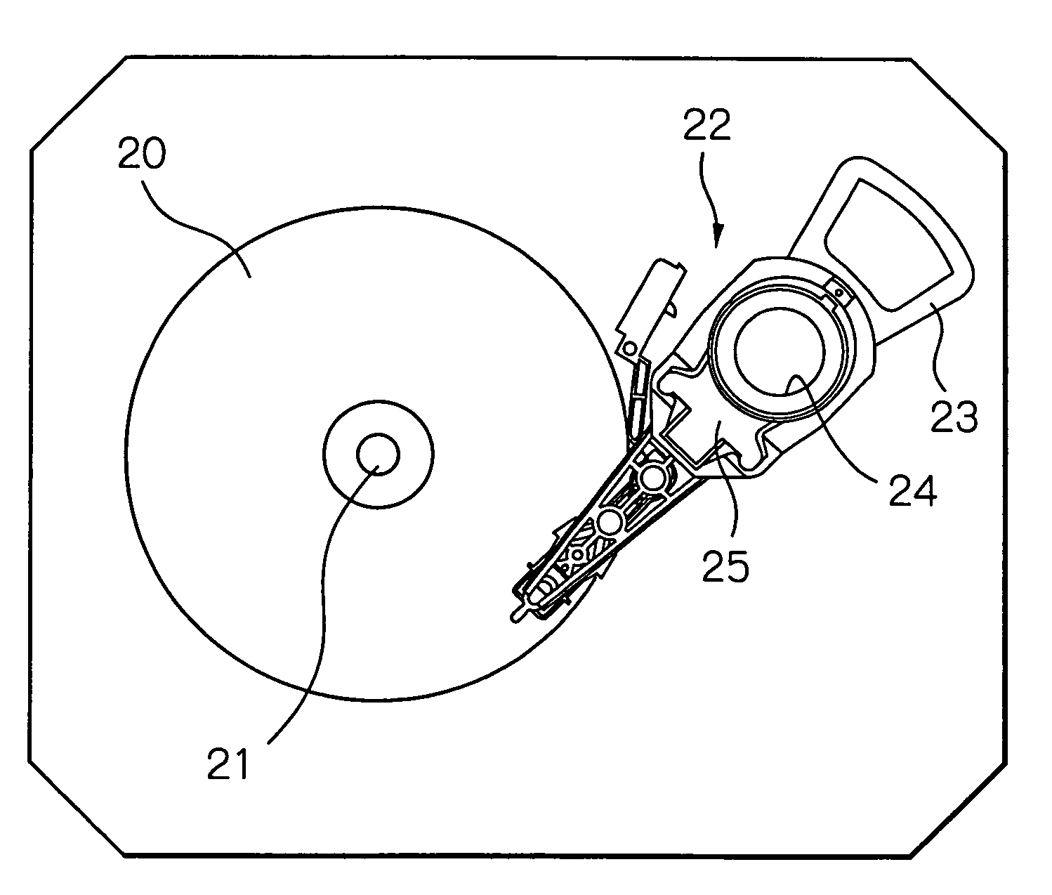
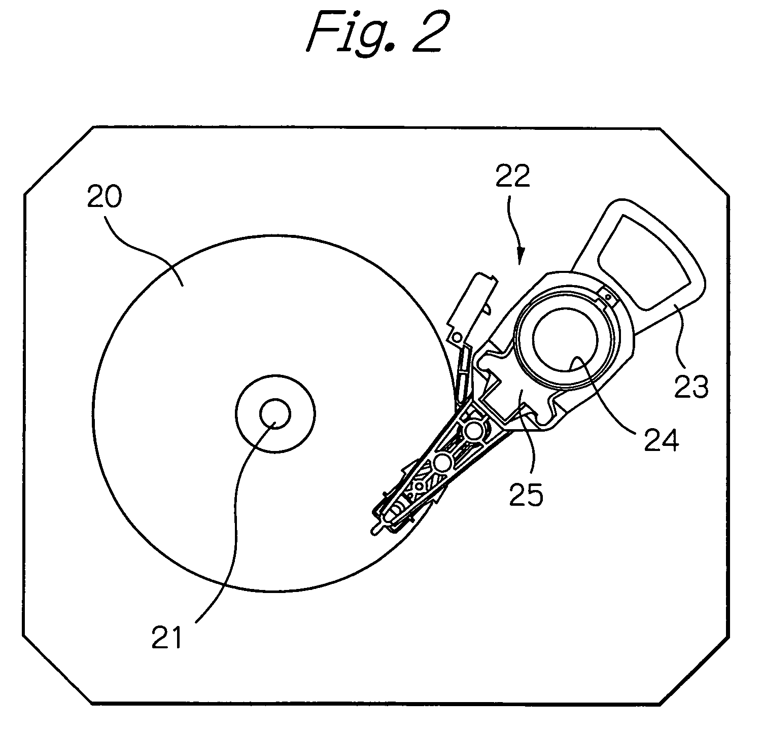
[0051]FIG. 2 schematically illustrates a configuration of a main part of a magnetic disk drive apparatus as a preferred embodiment according to the present invention, FIGS. 3a to 3d illustrate two HAAs mounted in the magnetic disk drive apparatus shown in FIG. 2, FIGS. 4 and 5 illustrate the two HAAS, FIG. 6 illustrates the two HAAs as seen from the opposite direction, and FIGS. 7 and 8 illustrate two HAAs and a VCM coil section mounted in the magnetic disk drive apparatus shown in FIG. 2. In all these figures, the illustration of a wiring pattern is omitted.

[0052]In FIG. 2, reference numeral 20 designates a single magnetic disk with a diameter of about 1 inch, which rotates around a shaft 21. Reference numeral 22 designates two HAAs having two magnetic head sliders that are mounted at leading end sections of the respective HAAs and opposed to the respective surfaces of the single magnetic disk 20, and a single VCM coil section 23 mounted at the trailing end sections of the HAAs. Re...


PUM

PropertyMeasurementUnit
diameteraaaaaaaaaa
thicknessaaaaaaaaaa
thicknessaaaaaaaaaa

Abstract

A head support mechanism includes a rigid support arm, a suspension for supporting, at its leading end section, a head slider with at least one head element, the suspension having a balance structure that can be pivoted in a direction crossing a surface of a recording medium using as a fulcrum a load support point established between the suspension and the support arm, a load generation unit for generating a load applied to the load support point for pressing the head slider toward the surface of the recording medium, a horizontal rotation bearing unit for pivotally bearing the support arm and the suspension so that the support arm and the suspension are capable of rotatively moving in a direction parallel to the surface of the recording medium, and an weight unit coupled to a trailing end section of the suspension to match the center of gravity of the suspension including the head slider with the load support point. The weight unit is formed around at least a part of the periphery of the horizontal rotation-bearing unit.

Description

PRIORITY CLAIM[0001]This application claims priority from Japanese patent application No. 2003-346583, filed on Oct. 6, 2003, which is incorporated herein by reference.BACKGROUND OF THE INVENTION[0002]1. Field of the Invention[0003]The present invention relates to a head support mechanism provided by assembling a support arm and a suspension, a head arm assembly (HAA) provided by mounting a flying type head slider for supporting a recording and / or reproducing head element such as a thin-film magnetic head or an optical head on the head support mechanism, and a disk drive apparatus provided with the HAA.[0004]2. Description of the Related Art[0005]In a magnetic disk drive apparatus, at least one magnetic head slider attached to a leading end section of an HAA is flying on a surface of a rotating magnetic disk. In this state, a thin-film magnetic head element formed on the magnetic head slider records and / or reproduces data on / or from the magnetic disk.[0006]The HAA mainly has a magne...

Claims


Application Information

Patent Timeline
Patent Type & Authority Patents(United States)
IPC IPC(8): G11B5/55G11B21/21G11B5/48G11B5/596G11B21/08G11B21/16
CPCG11B5/4813G11B5/5569
Inventor HONDA, TAKASHIHIGUCHI, YOSHIHISAKURIHARA, KATSUKIWADA, TAKESHI
Owner TDK CORPARATION
Features
  • R&D
  • Intellectual Property
  • Life Sciences
  • Materials
  • Tech Scout
  • Unparalleled Data Quality
  • Higher Quality Content
  • 60% Fewer Hallucinations
Learn More