Check patentability & draft patents in minutes with Patsnap Eureka AI!

Self-cleaning optical sensor

a self-cleaning, optical sensor technology, applied in the field of optical sensors, can solve the problems of high labor intensity, time-consuming and expensive, and disruption of measuremen

Inactive Publication Date: 2008-05-20
KISTLER HLDG AG
View PDF9 Cites 3 Cited by
  • Summary
  • Abstract
  • Description
  • Claims
  • Application Information

AI Technical Summary

Problems solved by technology

Because regulations of engine exhaust are becoming more and more restrictive, much effort is devoted to decrease soot formation during combustion in engines.
This process disrupts the measurement, is very time consuming and expensive.
In most cases this gas flow is unfortunately not sufficient to burn the front lens clean.

Method used


Image

  • Self-cleaning optical sensor
  • Self-cleaning optical sensor

Examples


Embodiment Construction

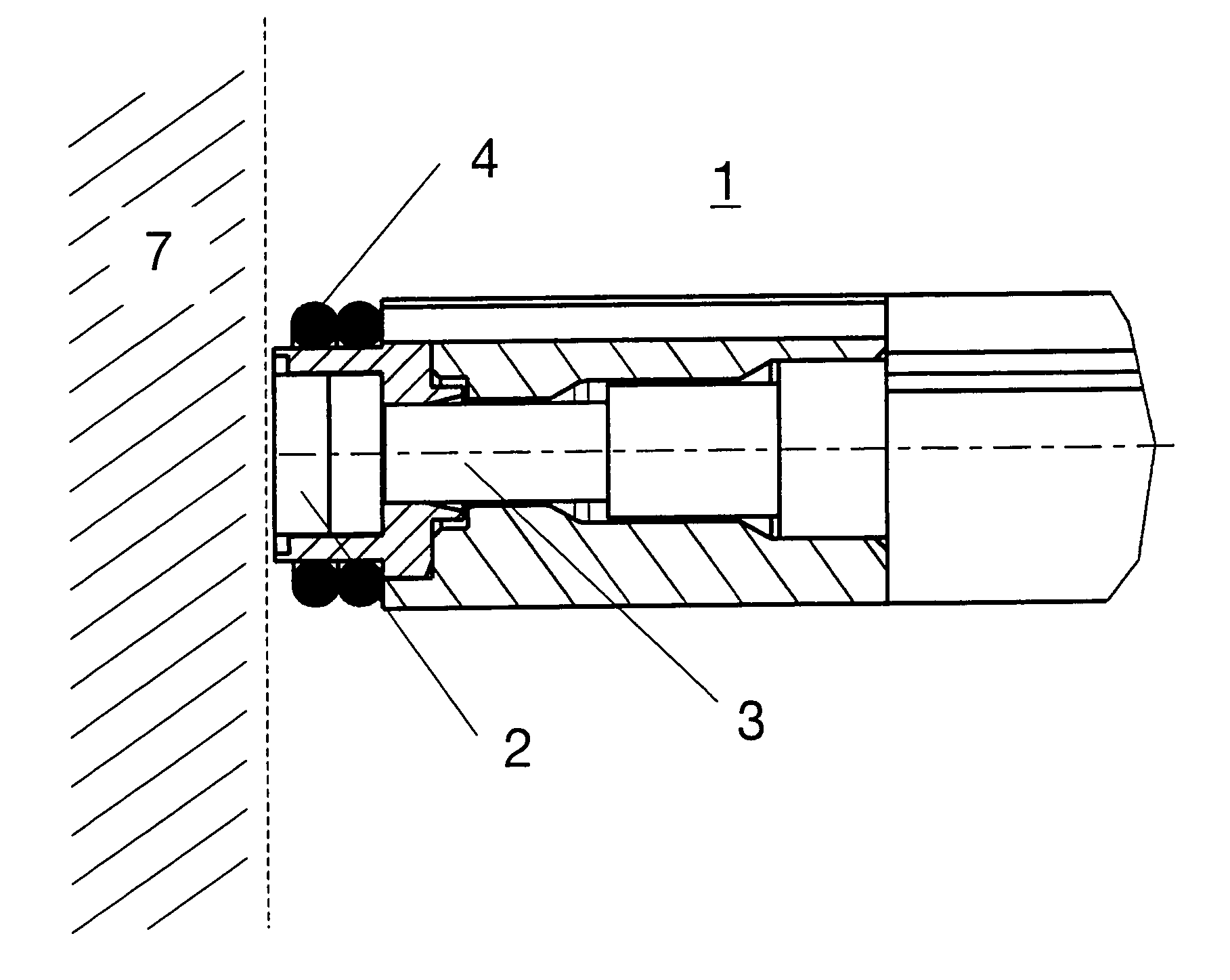
[0012]FIG. 1 shows an optical sensor indicated generally by the numeral 1. This sensor is configured with one or more lenses 2 disposed at the side facing the combustion chamber, which is generally designated by the numeral 7. The light coming in through the lenses 2 is transmitted by an optical fiber (designated 3 in FIG. 2) in the center of the sensor 1 and subsequently processed for analysis.

[0013]In the course of a measurement, the front surface of lens 2 of sensor 1 will be soiled by soot from the combustion chamber 7. This embodiment of the present invention has a heating mechanism 4 at the tip of the sensor 1 in the region of the front lens 2. The invention resides in that the sensor tip may be heated by said heating mechanism 4 to a temperature that ensures that the soot at the front lens 2 is burnt away. Thereby the sensor 1 may be kept clean and operational during the entire desired measurement period.

[0014]In this embodiment the heating mechanism 4 consists of a heating c...


PUM

PropertyMeasurementUnit
diameteraaaaaaaaaa
heating poweraaaaaaaaaa

Abstract

The invention relates to an optical sensor for detecting light emission in combustion processes in a combustion chamber. At least one lens of the sensor faces the combustion chamber and is disposed on the tip of the sensor. The inventive sensor is provided with a heating device, which is disposed on the tip thereof, in the region of the front lens. The heating device can be a wire coil, a laser or a conduit with heated fluid. The sensor can include a controller for controlling the temperature of the heating device so that the tip of the sensor can be heated by the heating device to a specific temperature at which any soot on the front lens is combusted. As a result, the sensor remains clean and operational during the entire measuring period as desired.

Description

CROSS-REFERENCE TO RELATED APPLICATIONS[0001]This application claims priority from previously filed PCT application No. PCT / CH2004 / 000142 filed on Mar. 11, 2004, which claims priority from CH 416 / 03, filed Mar. 13, 2003.STATEMENT REGARDING FEDERALLY SPONSORED RESEARCH OR DEVELOPMENT[0002]N / ABACKGROUND OF THE INVENTION[0003]The invention relates to an optical sensor for detecting the light intensity of combustion processes in a combustion chamber.[0004]In combustion engines, for example in spark ignition engines or diesel engines, optical sensors are used to monitor the combustion. The temporal recording of the light intensity in a combustion chamber provides important data as boundary conditions for computer models, since one might use the light intensity to derive the temperature. The detection of the light intensity also correlates to the soot concentration in the combustion chamber. Because regulations of engine exhaust are becoming more and more restrictive, much effort is devot...

Claims


Application Information

Patent Timeline
Patent Type & Authority Patents(United States)
IPC IPC(8): G01L23/16G01L23/22G01M15/00G01M15/10
CPCG01M15/10
Inventor KARST, DIETER
Owner KISTLER HLDG AG
Features
  • R&D
  • Intellectual Property
  • Life Sciences
  • Materials
  • Tech Scout
  • Unparalleled Data Quality
  • Higher Quality Content
  • 60% Fewer Hallucinations
Learn More