Supercharge Your Innovation With Domain-Expert AI Agents!

Method and apparatus for measuring hydrogen concentration in zirconium alloy components in the fuel pool of a nuclear power plant

a technology of zirconium alloy and fuel pool, which is applied in the direction of instruments, nuclear elements, greenhouse gas reduction, etc., can solve the problems of fissionable material release into the reactor coolant, limited use life of nuclear fuel rods, and uneven hydrogen concentration across the wall of the cladding, so as to eliminate uncertainty

Inactive Publication Date: 2008-06-17
ELECTRIC POWER RES INST INC
View PDF8 Cites 5 Cited by
  • Summary
  • Abstract
  • Description
  • Claims
  • Application Information

AI Technical Summary

Benefits of technology

Enables accurate, non-destructive, in-situ measurement of hydrogen concentration in nuclear fuel rod claddings, improving statistical representation and extending the useful life of fuel rods while reducing costs and errors associated with indirect methods.

Problems solved by technology

The useful lifetime of nuclear fuel rods is limited, in part, by the structural integrity of the zirconium alloy cladding encasing the radioactive material used to power the reactor.
However, the hydrogen concentration across the wall of the cladding is not uniform.
This embrittlement leaves the cladding material susceptible to cracking, potentially leading to release of fissionable material into the reactor coolant.
The current method for determining hydrogen concentration in nuclear fuel rods is a destructive method, involving cutting samples out of the rod.
The analysis is a slow and expensive analytical process, requiring skilled operators and complicated equipment.
This leads to a poor statistical representation of the fuel rod population, which may result in premature discharge of fuel rods, or more importantly, may lead to the use of fuel rods past their safe operating lifetime.
Therefore, while this method is accurate, the fact that it is destructive, requires off-site analysis, and is slow limits its usefulness.
However, these in-situ methods involve indirect measurements and assumptions which, if untrue, lead to large errors in hydrogen concentration.
This zirconium oxide thickness measurement, however, is subject to a number of sources of error.
First, there is often an additional surface layer, known as crud, formed by agglomeration of coolant corrosion products on the fuel cladding surface.
There are many sources of corrosion and wear products in a reactor system, including pumps, piping, and cladding.
The crud is not typically discernable from the zirconium oxide through eddy current methods since it is also a poor conductor, so the assessed oxide thickness is skewed by an amount equal to the thickness of the crud.
This results in an erroneously high zirconium oxide thickness measurement.
Because hydrogen concentration is correlated directly with zirconium oxide thickness, this also results in an erroneously high estimate of hydrogen level.
This could potentially lead to premature discharge of fuel rods and wasted money and resources.
A second condition that may be a source of error, related to crud deposition, is when ferromagnetic material is deposited onto the cladding surface.
Deposition of ferromagnetic material onto the surface of zirconium oxide leads to a distortion of the radio frequency energy applied through the probe and a change in the eddy current response, which results in an even greater overestimation of zirconium oxide layer thickness.
Neither of these assumptions is typically true, which leads to errors in estimation of oxide thickness and in hydrogen content.
Such assumptions may lead to errors in calibration of 15% or more, depending on the actual circumstances.
However, theses methods still do not directly measure the parameter of interest, hydrogen concentration.
In addition, U.S. Pat. No. 6,541,964 does not address a number of key complications, including fuel rod temperature, temperature gradients, and inhomogeneous hydrogen concentrations.

Method used


Image

  • Method and apparatus for measuring hydrogen concentration in zirconium alloy components in the fuel pool of a nuclear power plant
  • Method and apparatus for measuring hydrogen concentration in zirconium alloy components in the fuel pool of a nuclear power plant
  • Method and apparatus for measuring hydrogen concentration in zirconium alloy components in the fuel pool of a nuclear power plant

Examples


Embodiment Construction

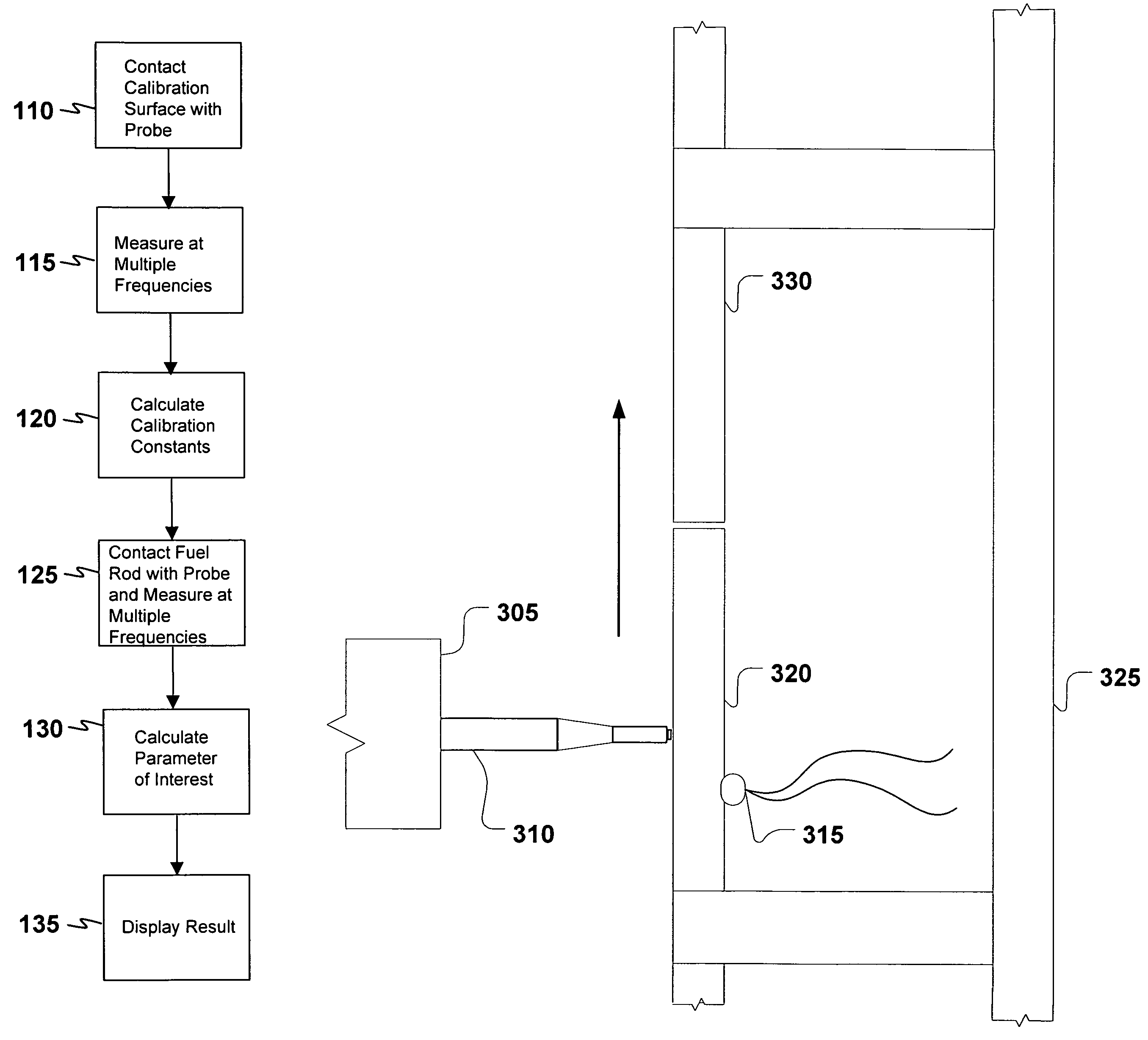
[0019]The present invention provides a method for measuring any parameter of interest in a particular sample using an eddy current probe. For example, the probe may be used to measure hydrogen concentration in a piece or section of metal, such as the hydrogen concentration in the cladding of a nuclear fuel rod. Generally, the eddy current probe is calibrated using a calibration standard that provides varying amounts of the parameter of interest in a material or substrate that represents the sample to be measured. For example, the calibration standard may be a piece of metal having varying hydrogen concentrations similar to the piece of metal or sample to be measured. The calibrated probe is then used to measure the parameter of interest in a given sample.

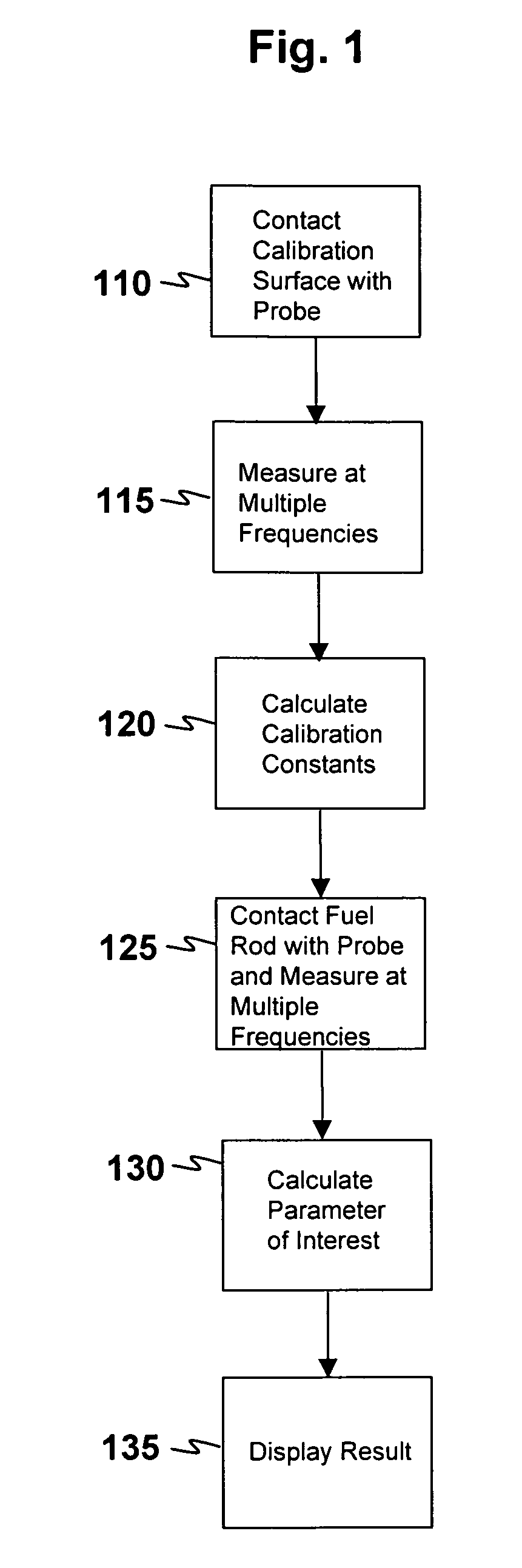
[0020]FIG. 1 is a process flow diagram according to one embodiment of the present invention. FIG. 1 provides an overview of one embodiment of a process that may be followed to obtain a measurement of hydrogen concentration in metal....


PUM


Abstract

The present invention provides a method for measuring hydrogen concentration in an electrically conductive material, such as a nuclear fuel rod, comprising calibrating an eddy current probe at a plurality of hydrogen concentrations; measuring eddy currents at a plurality of positions along an electrically conductive material; and calculating a hydrogen concentration in the electrically conductive material at each of the positions along the electrically conductive material. The present invention also provides a system for measuring hydrogen concentration in a nuclear fuel rod, comprising an eddy current probe; a nuclear fuel rod calibration standard; a data handling system for collecting data generated by the eddy current probe and for performing calculations using the data. The system may be utilized in-situ and may comprise a movable probe mount configured to hold the eddy current probe and to traverse the calibration standard and the nuclear fuel rod to be measured.

Description

BACKGROUND OF THE INVENTION[0001]1. Field of the Invention[0002]The present invention relates generally to a method of measuring hydrogen concentration in conductive materials. In particular, the present invention relates to a method of measuring hydrogen concentration in nuclear fuel rod claddings using eddy current techniques.[0003]2. Description of the Related Art[0004]The useful lifetime of nuclear fuel rods is limited, in part, by the structural integrity of the zirconium alloy cladding encasing the radioactive material used to power the reactor. One measure of the structural integrity of the zirconium alloy cladding is the hydrogen concentration in the cladding. Hydrogen concentration is important because hydrogen precipitates as a brittle second phase. An average concentration across the cladding wall on the order of 600 parts per million (ppm) leads to measurable hydrogen embrittlement. However, the hydrogen concentration across the wall of the cladding is not uniform. The c...

Claims


Application Information

Patent Timeline
Patent Type & Authority Patents(United States)
IPC IPC(8): G01B7/06G01R33/12
CPCG01R33/028G21C17/06G01N33/20G21Y2002/201G21Y2002/202G21Y2002/204G21Y2002/304G21Y2004/30G21Y2004/40G21Y2004/504G01N33/208G01N33/2022Y02E30/30
Inventor EDSINGER, KURTYAGNIK, SURESH K.JOHNSON, DUANE P.
Owner ELECTRIC POWER RES INST INC
Features
  • R&D
  • Intellectual Property
  • Life Sciences
  • Materials
  • Tech Scout
  • Unparalleled Data Quality
  • Higher Quality Content
  • 60% Fewer Hallucinations
Learn More