Method for detecting a bit jam condition using a freely rotatable inertial mass

Inactive Publication Date: 2008-07-08
BLACK & DECKER INC
View PDF27 Cites 48 Cited by
  • Summary
  • Abstract
  • Description
  • Claims
  • Application Information

AI Technical Summary

Benefits of technology

[0005]In accordance with the present invention, an improved method is provided for controlling a power tool having a rotary shaft. The method includes: disposing an inertial mass in a housing of the power tool, such that the inertial mass is freely rotatable about an axis of rotation which is axially aligned with the rotary shaft of the tool; monitoring rotational motion of the power tool in relation to the inertial mass during operation of the power too

Problems solved by technology

Unfortunately, there are users who improperly use this type of power tool.
For instance, when a user is holding the tool upright while drilling downward, there is a tendency to relax the grip on the rear handle.
Unfortunately, when the rotating

Method used


Image

  • Method for detecting a bit jam condition using a freely rotatable inertial mass
  • Method for detecting a bit jam condition using a freely rotatable inertial mass
  • Method for detecting a bit jam condition using a freely rotatable inertial mass

Examples


Embodiment Construction

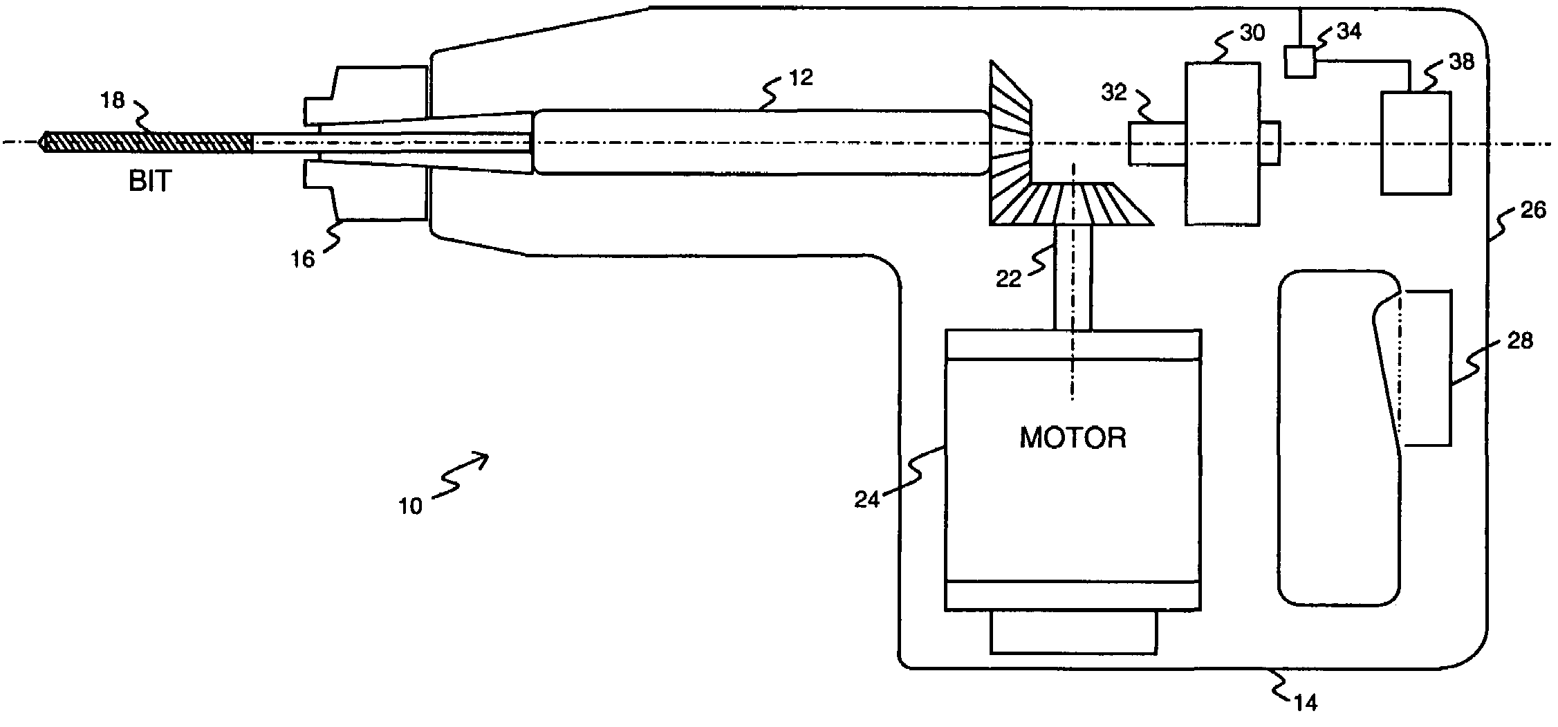
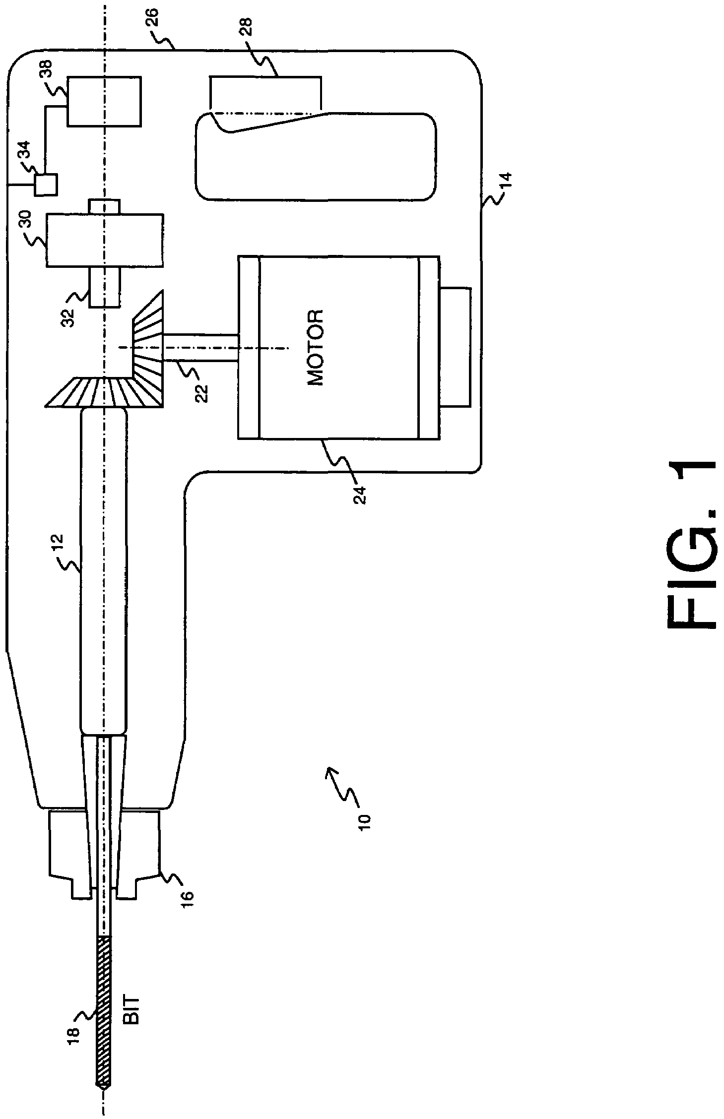
[0020]FIG. 1 illustrates an exemplary power tool 10 having a rotary shaft 12. In particular, the exemplary power tool is a rotary hammer. While the following description is provided with reference to a rotary hammer, it is readily understood that the broader aspects of the present invention are applicable to other types of power tools having rotary shafts.

[0021]The rotary hammer 10 is comprised of a housing 14 having an outwardly projecting front end and a rear end. A spindle (or rotary shaft) 12 extends axially through the front end of the housing 14. A bit holder 16 for securely holding a hammer bit 18 or other drilling tool is coupled at one end of the spindle 12; whereas a drive shaft 22 of an electric motor 24 is connected at the other end of the spindle 12. The rear end of the housing is formed in the shape of a handle 26. To activate operation of the tool, an operator actuated switch 28 is embedded in the handle 26 of the tool. Although only a few primary components of the ro...


PUM

PropertyMeasurementUnit
Angleaaaaaaaaaa
Timeaaaaaaaaaa
Massaaaaaaaaaa

Abstract

An improved method is provided for controlling a power tool having a rotary shaft. The method includes: disposing an inertial mass in a housing of the power tool, such that the inertial mass is freely rotatable about an axis of rotation which is axially aligned with the rotary shaft; monitoring rotational motion of the power tool in relation to the inertial mass during operation of the power tool; and activating a protective operation based on the rotational motion of the power tool in relation to the inertial mass.

Description

[0001]This application claims priority under 35 U.S.C. §119(e) to U.S. Provisional Application No. 60 / 465,064 filed on Apr. 24, 2003, and entitled “Safety Mechanism for a Rotary Hammer” the specification and drawings of which are hereby expressly incorporated by reference.FIELD OF THE INVENTION[0002]The present invention relates generally to a safety mechanism for a rotary hammer and, more particularly, to a method for detecting a bit jam condition in a power tool having a rotary shaft.BACKGROUND OF THE INVENTION[0003]The use of large rotary hammers is an effective way to bore holes into stone or concrete. Unfortunately, there are users who improperly use this type of power tool. For instance, when a user is holding the tool upright while drilling downward, there is a tendency to relax the grip on the rear handle. Since the rotational grab of the tool is minimized by the hammering action, it only takes a little force from the rear handle to stabilize the tool. The careless operator ...

Claims


Application Information

Patent Timeline
IPC IPC(8): B23B1/00B23B45/02B25F5/00
CPCB25F5/00Y10T408/14
Inventor CARRIER, DAVID APUZIO, DANIELBRADUS, ROBERT
Owner BLACK & DECKER INC
Why Eureka
Try Eureka