Tape cartridge with visible management information
a management information and tape cartridge technology, applied in the field of tape cartridges, can solve the problems of degrading the efficiency of data management, labeling was very burdensome for users, and management information could not be changed withou
- Summary
- Abstract
- Description
- Claims
- Application Information
AI Technical Summary
Benefits of technology
Problems solved by technology
Method used
Image

Examples
first embodiment
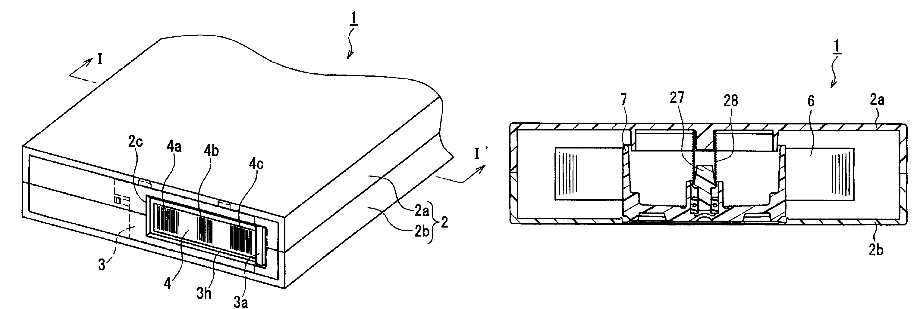
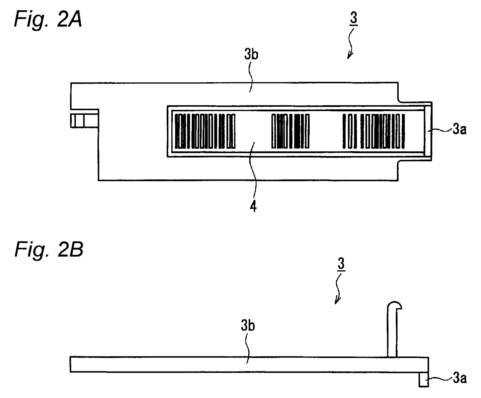
[0024]FIG. 1A is a perspective view showing a tape cartridge in this embodiment, while FIG. 1B is a cross sectional view taken along line I-I′ in FIG. 1A. FIG. 2A is a plane view showing a movable member constituting the tape cartridge in this embodiment, while FIG. 2B is a side view showing the same. FIG. 3A, FIG. 4A and FIG. 5A are rear views showing the tape cartridge shown in FIG. 1A, while FIG. 3B, FIG. 4B and FIG. 5B are plane views showing the tape cartridge shown in FIG. 1A without an upper cover 2a.
[0025]As shown in FIG. 1A and FIG. 1B, the tape cartridge 1 in the present embodiment is composed of a case 2 and a magnetic tape 6 stored in the case 2. The case 2 is formed from an upper cover 2a and a lower cover 2b which are joined by screws and the like. The magnetic tape 6, which is wound around a reel 7 that is rotatably housed in the case 2, is feedable from the case 2. In the case 2, the reel 7 is depressed downward as viewed in FIG. 1B by a helical compression spring 2...
second embodiment
[0044]FIG. 7 is a perspective view showing a tape cartridge in this embodiment, FIG. 8A, FIG. 9A and FIG. 10A are rear views showing the tape cartridge shown in FIG. 7, FIG. 8B, FIG. 9B and FIG. 10B are plane views showing the tape cartridge shown in FIG. 7 without an upper cover 2a of the case. It is to be noted that in FIG. 7, reference numeral 2b denotes a lower cover of the case.
[0045]As shown in FIG. 7, the tape cartridge in the present embodiment is identical in structure to the tape cartridge in the first embodiment except that a movable member 3 is a write protector member capable of blocking information recording onto the magnetic tape and that a sensor hole 2e is formed on the case 2. It is to be noted that in FIG. 7, there are shown a label 4, management information sets 4a to 4c, and an operation window 2c.
[0046]As shown in FIG. 7, in the tape cartridge 11 in the present embodiment, a sensor hole 2e is formed on, for example, a lateral face of the case 2. The propriety ...
third embodiment
[0052]FIG. 11A is a perspective view showing a tape cartridge in this embodiment, and FIG. 11B and FIG. 11C are perspective views showing one example of a movable member constituting the tape cartridge shown in FIG. 11A. FIG. 12 is a plane view showing the tape cartridge shown in FIG. 11A without an upper cover 2a of the case. FIG. 13A and FIG. 13B are perspective views showing other examples of the movable member constituting the tape cartridge in the present embodiment. FIG. 14 is a fragmentary cross sectional view showing the tape cartridge 111 shown in FIG. 11A. It is to be noted that reference numeral 2b denotes a lower cover of the case 2 in FIG. 11A and only a case is represented by a cross section in FIG. 14.
[0053]As shown in FIGS. 11A to 1C, in the tape cartridge 111 in the present invention, a movable member 31 is in an almost cylinder shape. The movable member 31 is fixed onto the case 2 rotatably around its central axis.
[0054]In the example shown in FIGS. 11B and 11C, a ...
PUM
| Property | Measurement | Unit |
|---|---|---|
| magnetic | aaaaa | aaaaa |
| shape | aaaaa | aaaaa |
| retention power | aaaaa | aaaaa |
Abstract
Description
Claims
Application Information
 - R&D
- Intellectual Property
- Life Sciences
- Materials
- Tech Scout
- Unparalleled Data Quality
- Higher Quality Content
- 60% Fewer Hallucinations
Browse by: Latest US Patents, China's latest patents, Technical Efficacy Thesaurus, Application Domain, Technology Topic, Popular Technical Reports.
© 2025 PatSnap. All rights reserved.Legal|Privacy policy|Modern Slavery Act Transparency Statement|Sitemap|About US| Contact US: help@patsnap.com