Integrated hinge and temporary door checker
- Summary
- Abstract
- Description
- Claims
- Application Information
AI Technical Summary
Benefits of technology
Problems solved by technology
Method used
Image

Examples
first embodiment
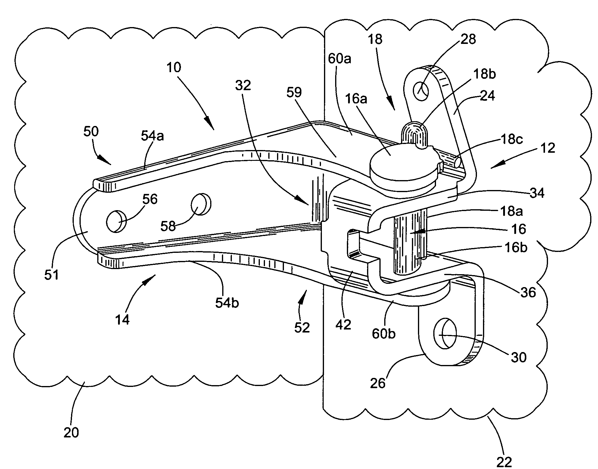
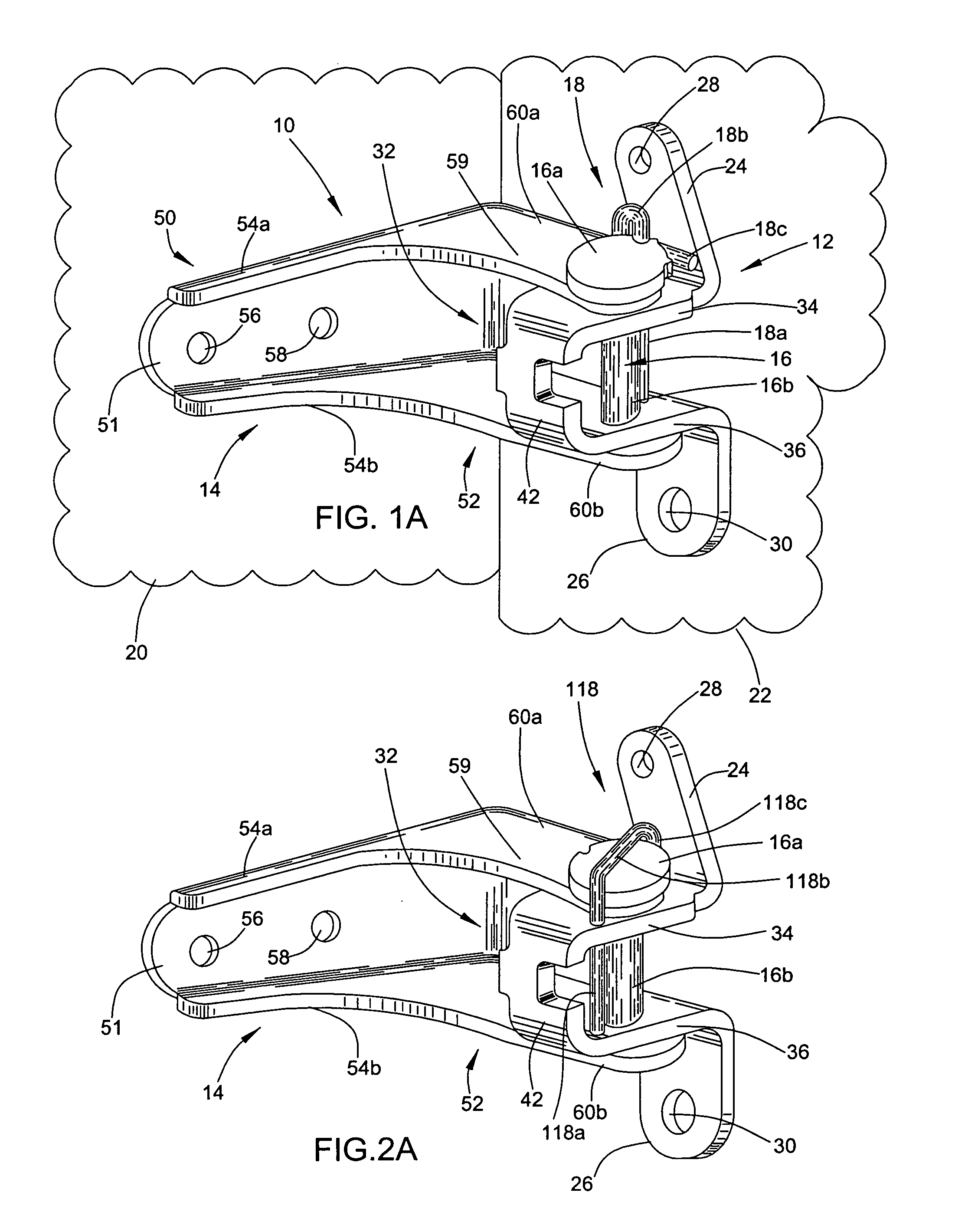
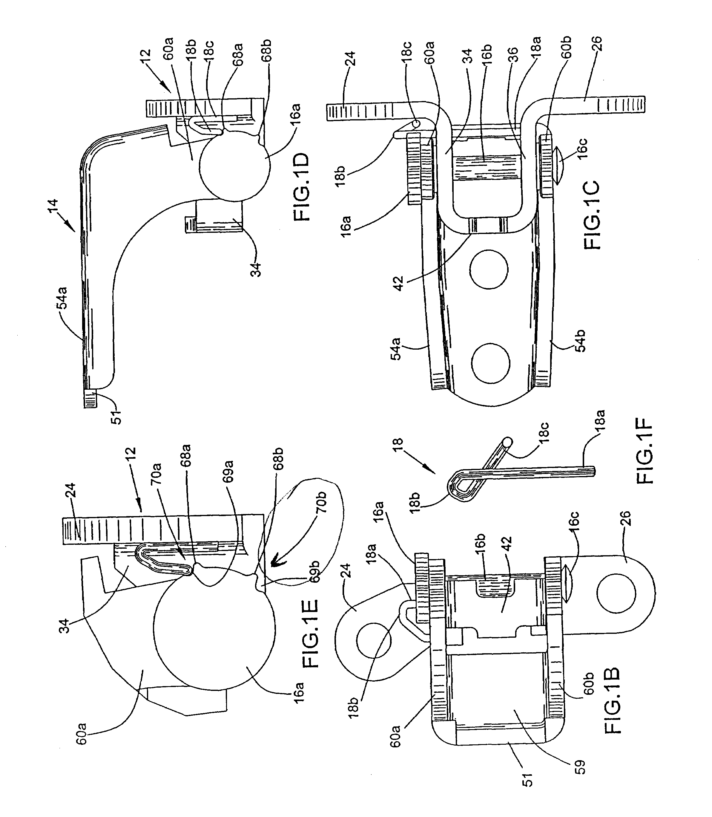
[0056]the present invention is illustrated in FIGS. 1A-1F, and is described hereinafter.
[0057]With reference to FIGS. 1B-1E, the head 16a of the hinge pin 16 is shown to include first and second raised tabs or protrusions 68a, 68b and associated first and second recesses or notches 69a, 69b. The first and second notches and recesses will hereafter be referred to as the first and second engagement points 70a, 70b.
[0058]With reference to FIG. 1F, the latching device 18 includes a lower leg 18a, an upper bend 18b curling around a loop of more than 180 degrees, and an upper arm 18c. The lower leg extends through aligned holes formed in the upper and lower legs 34, 36 of the U-shaped member 32 of the door hinge bracket 12. The upper bend 18b and the upper arm 18c are disposed above the upper leg 34 of the door hinge bracket U-shaped member 32, and adjacent the first or upper ear 24 of the door hinge bracket. It will be appreciated that the latching device 18 is preferably formed from a ...
second embodiment
[0062]the present invention is illustrated in FIGS. 2A-2F, and is described hereinafter.
[0063]With reference to FIGS. 2B-2E, the head 16a of the hinge pin 16 is shown to include first and second recesses or notches 78a, 78b and associated first and second radially extending raised tabs or protrusions 79a, 79b. The first and second notches and recesses will hereafter be referred to as the first and second engagement points 168a, 168b.
[0064]With reference to FIG. 2F, the latching device 118 is somewhat J-shaped, and includes a lower leg 118a, an interconnecting portion 118b, and an upper arm 118c. The lower leg 118a extends through aligned holes formed in the upper and lower legs 34, 36 of the U-shaped member 32 of the door hinge bracket 12. It is noted that the aligned holes are formed in the upper and lower legs 34, 36 relatively close to the base 42, as illustrated best in FIG. 2A. The interconnecting portion 118b extends diagonally across the upper surface of the hinge pin head 1...
third embodiment
[0068]the present invention is illustrated in FIGS. 3A-3F, and is described hereinafter.
[0069]With reference to FIGS. 3B-3E, the upper raised peripheral wall 60a of the pillar hinge bracket 14 is shown to include first and second recesses or notches 178a, 178b. The first and second notches and recesses may hereafter be referred to as the first and second engagement points 268a, 268b.
[0070]With reference to FIG. 3F, the latching device 218 includes a lower leg 218a, an interconnecting securement portion 218b, and an upper leg arm 218c. The upper leg 218c extends through a hole in the upper leg 34 of the U-shaped member 32 of the door hinge bracket 12. The lower leg 218a extends through a hole formed in the lower leg 36 of the U-shaped member of the door hinge bracket 12. The interconnecting securement portion 218b, which serves as a spring to force or bias the upper and lower legs 218c, 218a away from one another, extends across the door hinge bracket 12 and rests against the base 4...
PUM
 Abstract
Description
Claims
Application Information
 - R&D Engineer
- R&D Manager
- IP Professional
- Industry Leading Data Capabilities
- Powerful AI technology
- Patent DNA Extraction
Browse by: Latest US Patents, China's latest patents, Technical Efficacy Thesaurus, Application Domain, Technology Topic.
© 2024 PatSnap. All rights reserved.Legal|Privacy policy|Modern Slavery Act Transparency Statement|Sitemap