Supercharge Your Innovation With Domain-Expert AI Agents!

Image forming apparatus provided with a cooling mechanism for cooling portions

a technology of cooling mechanism and cooling portion, which is applied in the direction of electrographic process apparatus, instruments, optics, etc., can solve the problems of insufficient cooling of paper and high temperature, serious problem of paper delivery temperature, and very hot fixing unit during fixing operation

Inactive Publication Date: 2009-05-26
KK TOSHIBA +1
View PDF15 Cites 0 Cited by
  • Summary
  • Abstract
  • Description
  • Claims
  • Application Information

AI Technical Summary

Benefits of technology

Ensures uniform temperature distribution in delivered paper, reducing the risk of image defects and user discomfort by effectively cooling high-temperature areas, with temperatures below 75°C for double-face printing.

Problems solved by technology

However, if sufficient time is not secured between the fixing and delivery, the paper is insufficiently cooled and delivered with high temperature.
Particularly, in an image forming apparatus having a fixing and a delivery unit closely arranged, paper delivery temperature is a serious issue.
However, conventionally, when air-cooling a sheet of paper to be delivered, cooling air was blown to the entire sheet of paper, therefore, a sheet of paper may be delivered with high-temperature portions thereof not insufficiently cooled.
In particular, a fixing unit becomes very hot during a fixing operation.
For example, if image forming is repeated many times, the temperature of the photographic fixing unit reaches 160 to 170° C. If no cooling is performed, a paper delivery roller mounted on the outlet side of the fixing unit and a delivered sheet of paper reach about 100° C. If a sheet of paper is maintained at such a high temperature, there occur problems such as stripes of the paper delivery roller left on a formed image and the like.
Further, the high temperature portions are not cooled immediately, and therefore, a user may come into contact with the hot portions when removing a jammed sheet of paper and the like.

Method used


Image

  • Image forming apparatus provided with a cooling mechanism for cooling portions
  • Image forming apparatus provided with a cooling mechanism for cooling portions
  • Image forming apparatus provided with a cooling mechanism for cooling portions

Examples


Embodiment Construction

[0016]Throughout this description, the embodiments and examples shown should be considered as exemplars, rather than limitations on the apparatus and methods of the present invention.

[0017]Now, embodiments of the present invention will be described with reference to the accompanying drawings, in which like reference characters denotes like parts in the various views. Overlapping descriptions will be omitted.

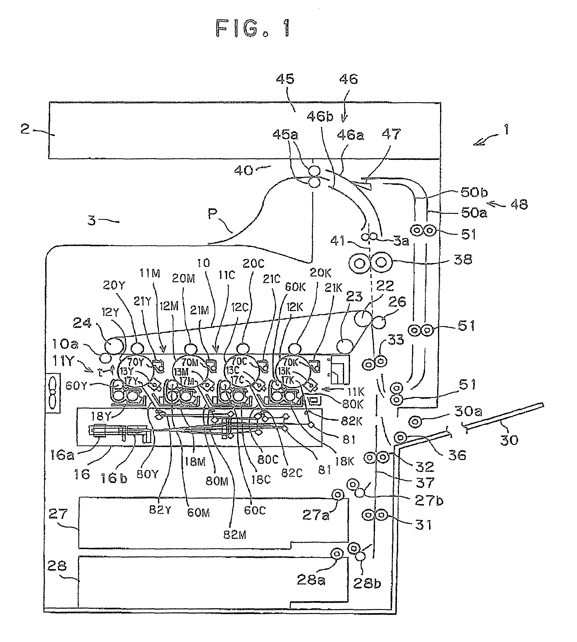
[0018]FIG. 1 is a schematic configuration view showing a 4-unit tandem color copying machine 1 which is an embodiment of the present invention and is an image forming apparatus. As shown in FIG. 1, the color copying machine 1 comprises a scanner section 2 and an intra-trunk paper delivery section 3 arranged in an upper part thereof. The color copying machine 1 further comprises four image forming units 11K to 11C arranged in parallel below an intermediate transfer belt 10, which is an intermediate transfer medium.

[0019]The image forming units 11K to 11C have respective photosensi...


PUM


Abstract

An image forming apparatus is provided with a cooling mechanism mechanism having an air-cooling fan and a cooling duct for guiding cooling air from this air-cooling fan to desired positions to be cooled. A plurality of rectangular holes are formed in the longitudinal direction of the cooling duct. Positions of the rectangular holes are not located directly above the respective paper delivery rollers and are slightly shifted from the paper delivery rollers toward the rear side. On the front side of the cooling duct there are formed an opening for discharging cooling air toward the ADU and an opening for discharging cooling air toward the rear side of the control panel operated by a user.

Description

CROSS-REFERENCE TO RELATED APPLICATION[0001]This application is based upon and claims the benefit of priority from prior Japanese Patent Application No. 2006-042767 filed on 20 Feb. 2006, the entire content of which is incorporated herein by reference.BACKGROUND OF THE INVENTION[0002]1. Field of the Invention[0003]The present invention relates to an image forming apparatus, and in particular to an image forming apparatus provided with a cooling mechanism for cooling portions which are very likely to be handled by users.[0004]2. Description of the Related Art[0005]In an image forming apparatus, sheet of paper is heated at the time of fixing. Subsequently the paper is cooled when it is fed and is then delivered. However, if sufficient time is not secured between the fixing and delivery, the paper is insufficiently cooled and delivered with high temperature. Particularly, in an image forming apparatus having a fixing and a delivery unit closely arranged, paper delivery temperature is a...

Claims


Application Information

Patent Timeline
Patent Type & Authority Patents(United States)
IPC IPC(8): G03G21/20
CPCG03G21/206G03G2221/1645
Inventor YOKOYAMA, SHUJI
Owner KK TOSHIBA
Features
  • R&D
  • Intellectual Property
  • Life Sciences
  • Materials
  • Tech Scout
  • Unparalleled Data Quality
  • Higher Quality Content
  • 60% Fewer Hallucinations
Learn More