Check patentability & draft patents in minutes with Patsnap Eureka AI!

Method for recording data in optical recording medium, an apparatus for recording data in optical recording medium and optical recording medium

a technology of which is applied in the field of an apparatus for recording data in optical recording medium and optical recording medium, can solve the problems of difficult to form a good shape recording mark, high output, and high cost of semiconductor lasers that emit laser beams having wavelength equal or shorter than 450 nm, and achieve high linear recording velocity.

Inactive Publication Date: 2009-06-30
TDK CORPARATION
View PDF13 Cites 0 Cited by
  • Summary
  • Abstract
  • Description
  • Claims
  • Application Information

AI Technical Summary

Benefits of technology

This approach enables data recording at linear velocities of 5 m / sec or higher with lower recording power, utilizing inexpensive semiconductor lasers and achieving high data transfer rates while maintaining signal quality and storage reliability.

Problems solved by technology

Since data are recorded in a DVD-R at a higher linear recording velocity than when recording data in a CD-R, unlike the case of recording data in a CD-R, it is difficult to form a recording mark having a good shape using a recording pulse having a width corresponding to the length of the recording mark M to be formed.
However, the output of a semiconductor laser emitting a laser beam having a wavelength equal to or shorter than 450 nm is smaller than that of a semiconductor laser emitting a laser beam having a wavelength of 780 nm for a CD and that of a semiconductor laser emitting a laser beam having a wavelength of 650 nm for a DVD, and a semiconductor laser that emits a laser beam having a wavelength equal to or shorter than 450 nm and has a high output is expensive.
Therefore, it is difficult to record data in a next-generation type optical recording medium using the basic pulse train pattern at a high data transfer rate and this problem is particularly serious when recording data at a linear recording velocity equal to or higher than 5 m / sec.

Method used


Image

  • Method for recording data in optical recording medium, an apparatus for recording data in optical recording medium and optical recording medium
  • Method for recording data in optical recording medium, an apparatus for recording data in optical recording medium and optical recording medium
  • Method for recording data in optical recording medium, an apparatus for recording data in optical recording medium and optical recording medium

Examples


working example 1

[0181]The thus fabricated optical recording medium was set in an optical recording medium evaluation apparatus “DDU1000” (Product Name) manufactured by Pulstec Industrial Co., Ltd. Then, a blue laser beam having a wavelength of 405 nm was employed as the laser beam for recording data and the laser beam was condensed onto the optical recording medium via the light transmission layer using an objective lens whose numerical aperture was 0.85, and data were recorded therein under the following recording signal conditions.

[0182]Modulation Code: (1.7) RLL

[0183]Channel Bit Length: 0.12 μm

[0184]Linear Recording Velocity: 5.3 m / sec

[0185]Channel Clock: 66 MHz

[0186]Recording Signal: random signal including a 2 T signal to an 8 T signal in no particular order

[0187]Data were recorded by modulating a laser beam in accordance with the first pulse train pattern including (n−1) divided pulses as a recording pulse wherein n was an integer of 2 to 8, varying the first bottom power Pb1 between 0.5 mW, ...

working example 2

[0190]Data were recorded in the optical recording medium similarly to in Working Example 1 except that the following recording conditions were employed. Then, the optimum recording power Pw was determined as the power of a laser beam when jitter was minimum and the relationship between the optimum recording power Pw and the first bottom power Pb1 was determined.

[0191]Modulation Code: (1.7) RLL

[0192]Channel Bit Length: 0.12 μm

[0193]Linear Recording Velocity: 10.6 m / sec

[0194]Channel Clock: 132 MHz

[0195]Recording Signal: random signal including a 2 T signal to an 8 T signal in no particular order

[0196]Under these recording conditions, the data transfer rate was about 70 Mbps when the format efficiency was 80% and the ratio of the shortest blank region interval to the linear recording velocity (shortest blank region interval / linear recording velocity) was 15.2 nsec.

[0197]The results of the measurement in Working Examples 1 and 2 are shown in FIG. 6.

[0198]As shown in FIG. 6, it was found...

working example 3

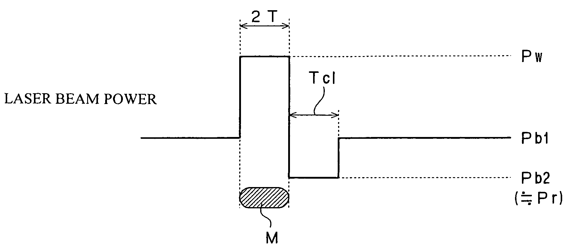
[0201]Data were recorded in the optical recording medium similarly to in Working Examples 1 and 2 except that the power of a laser beam was modulated in accordance with the second pulse train pattern. Then, the optimum recording power Pw was determined as the power of a laser beam when jitter was minimum and the relationship between the optimum recording power Pw and the first bottom power Pb1 was determined.

[0202]Here, the length of the cooling interval Tcl was set to 1 T and the second bottom power Pb2 was set to 0.1 mW.

[0203]The results of the measurement are shown in FIG. 7.

[0204]As shown in FIG. 7, it was found that when data were recorded by modulating the power of the laser beam in accordance with the second pulse train pattern, the level of the optimum recording power Pw became lower as the first bottom power Pb1 was set to a higher level and that when the data transfer rate was about 70 Mbps, the level of the optimum recording power Pw was markedly lowered in accordance wit...


PUM

PropertyMeasurementUnit
linear recording velocityaaaaaaaaaa
wavelengthaaaaaaaaaa

Abstract

It is an object of the present invention to provide a method for recording data in an optical recording medium which can record data in a write-once type optical recording medium at a high linear recording velocity using a laser beam whose recording power is set low. The method for recording data in an optical recording medium according to the present invention is constituted so that data are recorded by a laser beam whose power is modulated in accordance with a pulse train pattern onto an optical recording medium including a substrate, a first recording layer, a second recording layer and a light transmission layer to form a recording mark wherein a recording pulse is divided into (n−1) divided pulses and the power of the laser beam is set to a recording power Pw at the peak of each of the divided pulses and set to a first bottom power Pb1 and the levels of the recording power Pw and the first bottom power Pb1 are determined so that a ratio Pb1 / Pw of the first bottom power Pb1 to the recording power Pw falls within a range of 0.1 to 0.5. When the power of a laser beam is modulated using such a pulse train pattern to record data in an optical recording medium, the heating of a recording layer by the laser beam having the recording power Pw can be augmented by the laser beam having the first bottom power Pb1 and therefore, even in the case where data are to be recorded in an optical recording medium at a high linear recording velocity, it is possible to record data in the optical recording medium at a high linear recording velocity using a semiconductor laser having a low output.

Description

BACKGROUND OF THE INVENTION[0001]1. Field of the Invention[0002]The present invention relates to a method for recording data in an optical recording medium, an apparatus for recording data in an optical recording medium and an optical recording medium, and particularly, to a method for recording data in a write-once type optical recording medium, an apparatus for recording data in a write-once type optical recording medium, and a write-once type optical recording medium.[0003]2. Description of the Related Art[0004]Optical recording media such as the CD, DVD and the like have been widely used as recording media for recording digital data. These optical recording media can be roughly classified into optical recording media such as the CD-ROM and the DVD-ROM that do not enable writing and rewriting of data (ROM type optical recording media), optical recording media such as the CD-R and DVD-R that enable writing but not rewriting of data (write-once type optical recording media), and op...

Claims


Application Information

Patent Timeline
Patent Type & Authority Patents(United States)
IPC IPC(8): G11B7/00G11B5/027G11B7/0045G11B7/1267
CPCG11B7/00456G11B7/1267G11B7/00455G11B7/0045G11B7/1263G11B7/24038G11B7/243
Inventor KATO, TATSUYAHIRATA, HIDEKI
Owner TDK CORPARATION
Features
  • R&D
  • Intellectual Property
  • Life Sciences
  • Materials
  • Tech Scout
  • Unparalleled Data Quality
  • Higher Quality Content
  • 60% Fewer Hallucinations
Learn More