Check patentability & draft patents in minutes with Patsnap Eureka AI!

Electric air pump for secondary air supply system

a secondary air supply and electric air pump technology, which is applied in the direction of positive displacement liquid engines, piston pumps, liquid fuel engines, etc., can solve the problem of difficulty in determining whether the temperature of the brush has decreased, and achieve the effect of accurately estimating the temperature of the brush

Inactive Publication Date: 2009-08-04
TOYOTA JIDOSHA KK
View PDF18 Cites 2 Cited by
  • Summary
  • Abstract
  • Description
  • Claims
  • Application Information

AI Technical Summary

Benefits of technology

[0007]It is an object of the invention to accurately estimate a temperature of a brush of a motor for an electric air pump employed for a secondary air supply system.
[0023]According to the invention as aforementioned, the temperature of the brush of the motor that drives the electric air pump for the secondary air supply system is estimated based on the brush temperature increase rate during the motor operation. As the temperature increase rate is obtained in accordance with the discharge pressure of the pump, the brush temperature can be accurately estimated.
[0024]In the above-structured invention, the brush temperature decrease after stopping the motor operation can be obtained based on the brush temperature decrease rate. This makes it possible to accurately estimate the brush temperature even after stopping the motor operation.
[0025]In the above-structured invention, the initial brush temperature can be accurately estimated by the initial brush temperature estimation unit.
[0026]In the above-structured invention, as each of the increase and the decrease in the brush temperature can be accumulated at the respective calculation cycles, the estimation can be accurately performed.

Problems solved by technology

It is difficult to determine whether the temperature of the brush has decreased to the temperature equal to or lower than an allowable value.

Method used


Image

  • Electric air pump for secondary air supply system
  • Electric air pump for secondary air supply system
  • Electric air pump for secondary air supply system

Examples


first embodiment

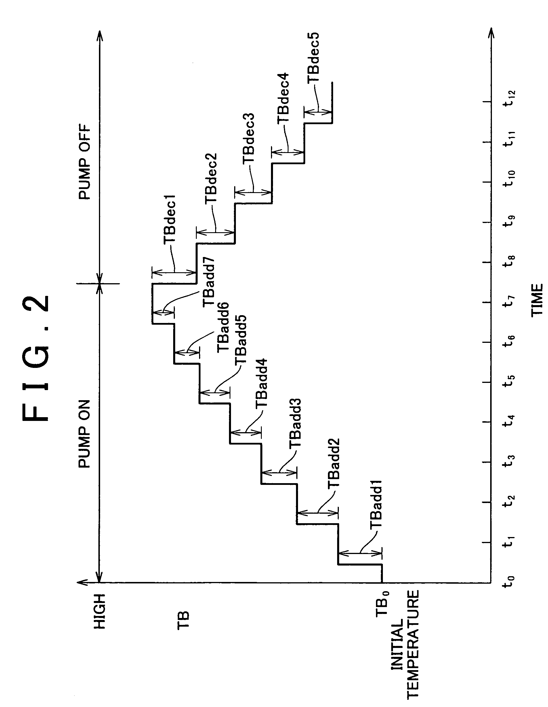
[0062]A first embodiment will be explained referring to FIG. 2 representing the concept thereof.

[0063]In FIG. 2, the air pump 10 is turned ON at time t0, and at time t7, the air pump 10 is turned OFF. The temperature of the brush is then detected at time t12.

[0064]Assuming that the brush temperature is TB, the initial temperature is TBo, the increase in the brush temperature is TBaddi at a predetermined time interval (calculation cycle), and the decrease in the brush temperature is TBdeci at a predetermined time interval (calculation cycle), the following equation is established:

TB=TBo+(TBadd1+ . . . +TBadd7)−(TBdec1+ . . . +TBdec5).

[0065]In the aforementioned case, the increase in the brush temperature is TBaddi, and the decrease in the brush temperature is TBdeci. The increase in the brush temperature (decrease in the brush temperature) is obtained by multiplying the brush temperature increase rate (brush temperature decrease rate) by a predetermined time. In this embodiment, the ...

second embodiment

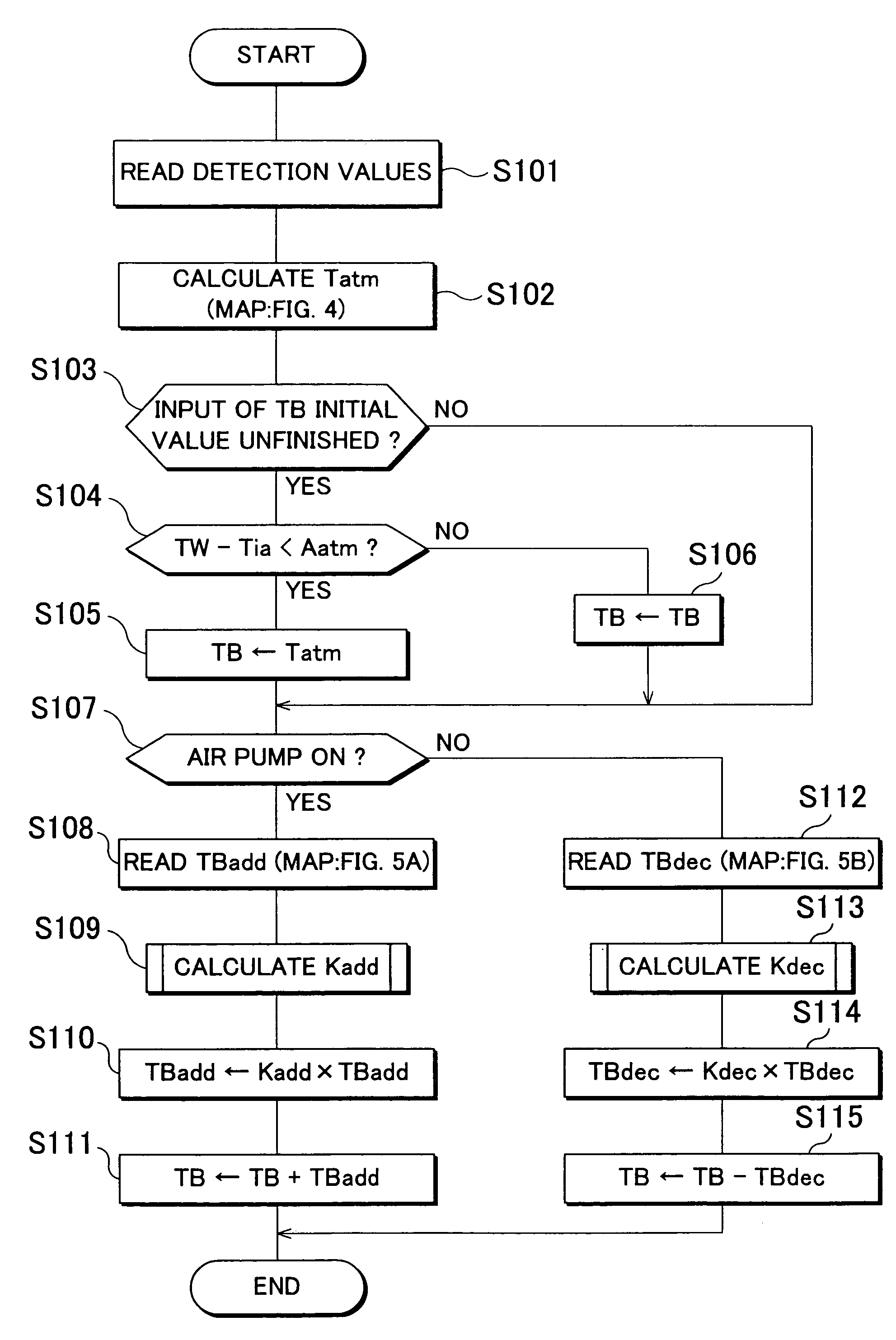
[0092]FIG. 14 is a flowchart of the control routine executed in the

[0093]The process executed in steps S201 to S204, and step S207 are the same as that executed in steps S101 to S104, and step S107 in the first embodiment. The process in steps S205 and S206 of the second embodiment is different from the process executed in steps of the first embodiment in that the atmospheric temperature Tatm, and a previous brush temperature TB are input to the initial value TBini, which is not updated in the course of the calculation routine.

[0094]In step S208, the average brush temperature increase rate MTBadd is calculated. It may be obtained by averaging the brush temperature increase rate Tbadd from map shown FIG. 5A at respective calculation cycles with the appropriate process. Alternatively each average value of the discharge pressure P of the air pump 10 and the brush temperature TB is obtained in the respective calculation cycles. Then the brush temperature increase rate TBadd correspondin...


PUM


Abstract

When an air pump is operated, a brush temperature increase rate stored in an ECU in relation to a discharge pressure of the air pump and a brush temperature is multiplied by a calculation cycle time, and the resultant value is cumulatively added. When the air pump is stopped, a brush temperature decrease rate stored in the ECU in relation to the brush temperature is multiplied by the calculation cycle time, and the resultant value is cumulatively added. Each of the cumulative values read from a map is added to and subtracted from an initial brush temperature value, respectively so as to estimate the brush temperature.

Description

INCORPORATION BY REFERENCE[0001]The disclosure of Japanese Patent Application No. 2004-133330 filed on Apr. 28, 2004, including the specification, drawings and abstract are incorporated herein by reference in its entirety.BACKGROUND OF THE INVENTION[0002]1. Field of Invention[0003]The invention relates to an electric air pump employed for a secondary air supply system, and more particularly, to an electric air pump having a motor with a brush.[0004]2. Description of Related Art[0005]An electric air pump having a motor with a brush is generally employed in a secondary air supply system for purifying the exhaust gas. It is necessary to prevent excessive heating of the brush of the motor for the electric pump so as to avoid the failure in the pump operation caused by the excessive temperature rise in the brush. The publication of JP-A-5-202889 discloses the art for blowing air to the brush so as to be cooled.[0006]In the art disclosed in the publication, the brush is blown by air, but ...

Claims


Application Information

Patent Timeline
Patent Type & Authority Patents(United States)
IPC IPC(8): F04B49/10F04B49/06H01R39/38F04B39/00F01N3/32F04B53/00
CPCF04B49/06
Inventor KOYAMA, HIROYASU
Owner TOYOTA JIDOSHA KK
Features
  • R&D
  • Intellectual Property
  • Life Sciences
  • Materials
  • Tech Scout
  • Unparalleled Data Quality
  • Higher Quality Content
  • 60% Fewer Hallucinations
Learn More