Supercharge Your Innovation With Domain-Expert AI Agents!

Semiconductor device and method for manufacturing the same

a technology of semiconductor devices and semiconductors, applied in semiconductor devices, semiconductor/solid-state device details, electrical apparatus, etc., can solve problems such as slow device operation speed, equipment or process environment contamination during subsequent processing, and defects in passivation films, so as to avoid contamination of processing equipment and process environment, and prevent exposure

Active Publication Date: 2009-08-18
TESSERA ADVANCED TECH
View PDF0 Cites 2 Cited by
  • Summary
  • Abstract
  • Description
  • Claims
  • Application Information

AI Technical Summary

Benefits of technology

Prevents contamination and defects by maintaining the copper alignment mark under protection, enhancing manufacturing yield and process integrity.

Problems solved by technology

Increased parasitic capacitance and resistance together slow the operational speed of a device.
For bonding pads, however, aluminum is typically deposited on a copper wiring layer, since copper is a poor alloy with gold and is thus unsuitable for bonding pad formation.
For example, defects in the passivation film may occur due to stresses generated when of scribing the wafer to render a plurality of devices or chips.
However, the copper lines of the alignment key are exposed, leading to potential contamination of equipment or the process environment during subsequent processing.
A copper alignment mark, exposed as a result of the removal of the passivation film in the scribe lane, may contaminate equipment or cause fatal defects, as shown in FIG. 2.

Method used


Image

  • Semiconductor device and method for manufacturing the same
  • Semiconductor device and method for manufacturing the same
  • Semiconductor device and method for manufacturing the same

Examples


Embodiment Construction

[0025]Reference will now be made in detail to exemplary embodiments of the present invention, examples of which are illustrated in the accompanying drawings. Wherever possible, like reference designations will be used throughout the drawings to refer to the same or similar parts.

[0026]FIGS. 3A-3E respectively illustrate a method for manufacturing a semiconductor device according to the present invention.

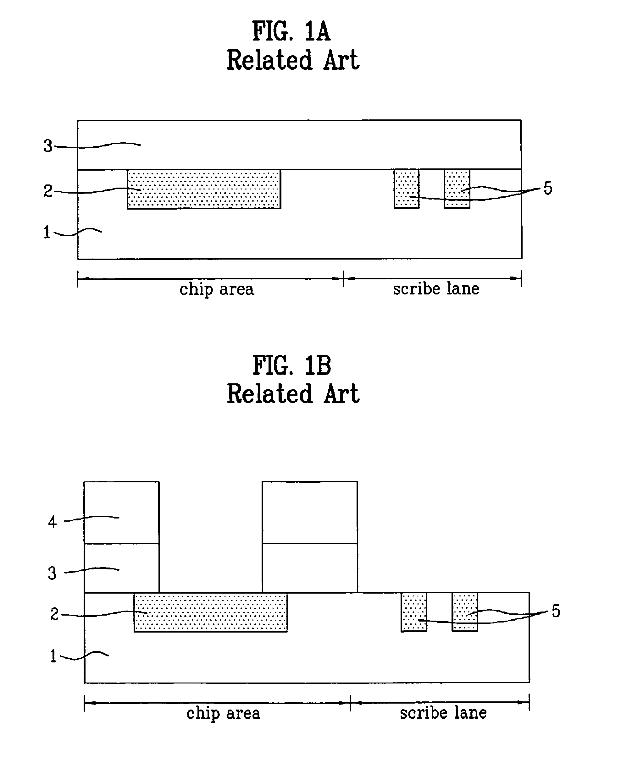
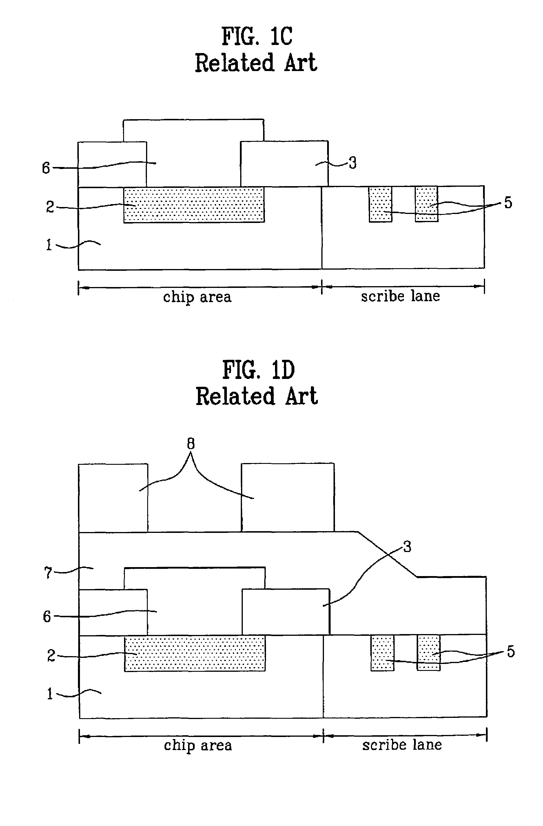
[0027]Referring to FIG. 3A, a dielectric film 21 is deposited on a semiconductor substrate (not shown), and a conductive film 22 is formed using a damascene process. An alignment mark 22a is formed in the scribe lane. The conductive film 22 and the alignment mark 22a may be both formed of copper. A first passivation film 23 and a second passivation film 24 are sequentially deposited on an entire surface of the substrate including the conductive film 22 and the alignment mark 22a. The first passivation film 23 and the second passivation film 24 may be formed of materials having differ...


PUM

PropertyMeasurementUnit
areaaaaaaaaaaa
conductiveaaaaaaaaaa
parasitic capacitanceaaaaaaaaaa

Abstract

A semiconductor device and a method manufacturing the same prevents copper from being exposed to a surface of a passivation film after a copper metal line formation, to avoid contamination of processing equipment and the process environment. The method includes providing a substrate with a scribe lane and a chip area in which metal wiring layers are formed, forming a dielectric film, forming a conductive film on the dielectric film in a chip area and an alignment mark on the dielectric film in a scribe lane, forming passivation films, exposing the conductive film by removing the passivation films in a bonding pad portion in a chip area, forming another conductive film in the bonding pad portion to electrically connect with the conductive film, forming another passivation film, and selectively removing the passivation films.

Description

[0001]This application claims the benefit of Korean Patent Application No. 10-2004-0114798, filed on Dec. 29, 2004, which is hereby incorporated by reference for all purposes as if fully set forth herein.BACKGROUND OF THE INVENTION[0002]1. Field of the Invention[0003]The present invention relates to semiconductor devices, and more particularly, to a semiconductor device and a method for manufacturing the same in which copper is prevented from being exposed to a surface of a passivation film after a Cu metal line formation, to avoid contaminating equipment or the process environment.[0004]2. Discussion of the Related Art[0005]With more highly integrated semiconductor devices, the parasitic capacitance of a dielectric film and the resistance of a metal line both increase. Increased parasitic capacitance and resistance together slow the operational speed of a device. Therefore, there has been a trend toward the use of lower-k dielectrics as an interlayer dielectric film and the use of ...

Claims


Application Information

Patent Timeline
Patent Type & Authority Patents(United States)
IPC IPC(8): H01L21/76
CPCH01L23/3192H01L23/544H01L24/03H01L24/05H01L2924/0002H01L2224/02166H01L2924/01033H01L2924/01019H01L2924/30105H01L2924/05042H01L2924/01082H01L2223/54453H01L2224/05001H01L2224/05073H01L2224/05567H01L2224/05571H01L2224/05624H01L2224/05647H01L2924/01013H01L2924/01014H01L2924/01029H01L2924/01079H01L2924/00014H01L2224/05552H01L21/768H01L21/28
Inventor KIM, YUNG PIL
Owner TESSERA ADVANCED TECH
Features
  • R&D
  • Intellectual Property
  • Life Sciences
  • Materials
  • Tech Scout
  • Unparalleled Data Quality
  • Higher Quality Content
  • 60% Fewer Hallucinations
Learn More