Composite emitting device
a composite emitting device and emitting device technology, which is applied in the direction of discharge tube luminescnet screens, discharge tube/lamp details, electric discharge lamps, etc., can solve the fundamental problem of the emitting device, the light emitted in directions other than the light-outcoupling direction a, cannot be outcoupled from the device, and can not be utilized. , to achieve the effect of high-efficiency composite emitting devices
- Summary
- Abstract
- Description
- Claims
- Application Information
AI Technical Summary
Benefits of technology
Problems solved by technology
Method used
Image


Examples
first embodiment
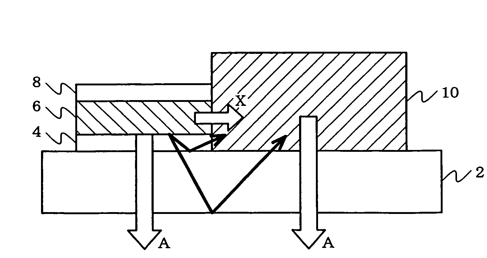
[0049]FIG. 1 is a view showing a composite emitting device according to one embodiment of the invention.
[0050]In FIG. 1, the reference numeral 2 indicates a transparent supporting substrate, the reference numeral 4 indicates a transparent electrode (first electrode), the reference numeral 6 indicates an organic luminescent medium (luminescent medium), the reference numeral 8 indicates a reflecting electrode (second electrode), and the reference numeral 10 indicates a fluorescent film. The composite emitting device includes a first emitting part in which the transparent electrode 4, the organic luminescent medium 6, and the reflecting electrode 8 are stacked on the supporting substrate 2 in this order in the light-outcoupling direction A, and a second emitting part including the fluorescent film 10 arranged adjacent to the first emitting part in the directions X and Y (directions substantially perpendicular to the light-outcoupling direction A).
[0051]The operation of the composite em...
second embodiment
[0056]FIG. 2 is a view showing a composite emitting device according to another embodiment of the invention.
[0057]In the following embodiments, the same members as shown in FIG. 1 are indicated by the same symbols. Description of these members is omitted.
[0058]In the composite emitting device according to the first embodiment, both the organic luminescent medium 6 and the fluorescent film 10 are placed between the transparent electrode 4 and the reflecting electrode 8. In the second embodiment, a fluorescent film 10 is not placed between a transparent electrode 4 and a reflecting electrode 8.
[0059]Specifically, as shown in FIG. 2, a first emitting part including a transparent electrode 4, an organic luminescent medium 6, and a reflecting electrode 8 and a second emitting part including a fluorescent film 10 are disposed on a supporting substrate 2.
[0060]In the device according to the second embodiment, the thickness of the fluorescent film 10 is increased in order to increase the co...
third embodiment
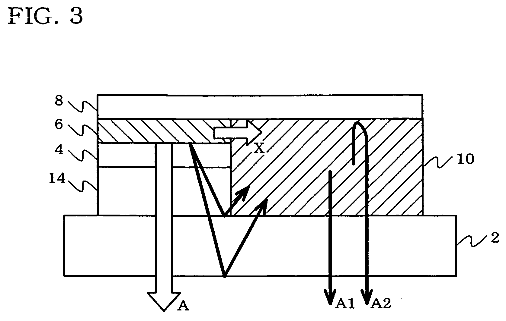
[0061]FIG. 3 is a view showing a composite emitting device according to still another embodiment of the invention.
[0062]In the device according to the third embodiment, a first emitting part including a transparent insulating film 14, a transparent electrode 4, an organic luminescent medium 6, and a reflecting electrode 8, and the second emitting part including a fluorescent film 10 and a reflecting electrode 8 are disposed on a supporting substrate 2. The thickness of the fluorescent film 10 is increased in order to increase the conversion efficiency of the fluorescent film 10 like the second embodiment.
[0063]As shown in FIG. 3, the back (upper) surfaces of the organic luminescent medium 6 and the fluorescent film 10 are made even by forming the transparent insulating film 14 between the transparent electrode 4 and the supporting substrate 2. Specifically, the thickness of the transparent insulating film 14 is adjusted so that the thickness of the fluorescent film 10 is equal to th...
PUM
 Abstract
Description
Claims
Application Information
 - R&D
- Intellectual Property
- Life Sciences
- Materials
- Tech Scout
- Unparalleled Data Quality
- Higher Quality Content
- 60% Fewer Hallucinations
Browse by: Latest US Patents, China's latest patents, Technical Efficacy Thesaurus, Application Domain, Technology Topic, Popular Technical Reports.
© 2025 PatSnap. All rights reserved.Legal|Privacy policy|Modern Slavery Act Transparency Statement|Sitemap|About US| Contact US: help@patsnap.com