Supercharge Your Innovation With Domain-Expert AI Agents!

Port sealing in a rotary valve

a technology of rotary valve and sealing arrangement, which is applied in the direction of valve arrangement, oscillatory slide valve, machine/engine, etc., can solve the problems of failure to develop a satisfactory gas sealing arrangement, port not being physically sealed from one another, and no commercial success

Inactive Publication Date: 2009-11-24
BISHOP INNOVATION PTY LTD
View PDF15 Cites 5 Cited by
  • Summary
  • Abstract
  • Description
  • Claims
  • Application Information

AI Technical Summary

Problems solved by technology

Large numbers of rotary valve arrangements have been proposed but none have achieved commercial success.
One of the major contributing factors to this lack of success is the failure to develop a satisfactory gas sealing arrangement.
However, in valves with both inlet and exhaust ports in the same valve this means that these ports were not physically sealed from one another.
In most cases the pressure in the exhaust port is larger than the pressure in the inlet port, and consequently leakage is predominantly from the exhaust port into the inlet port.
However, in some instances such as high performance engines even a small amount of leakage between the exhaust port and the inlet port is a problem as this leakage reduces engine power.
As a consequence, the pressure difference between the inlet and exhaust port is subject to rapid cyclic fluctuation through out the engine cycle.
In other instances, such as a production engine operating at idle, the amount of leakage between the exhaust port and the inlet port may be too great and adversely affect the smooth idle of the engine.
The low engine speed at idle means there is a relatively long period of time for exhaust to leak across the bridge into the inlet port.
The combination of high pressure difference and long time available for leakage means that in some instances excessive amounts of exhaust gas will leak into the inlet system.
Because of the nature of these engines, they require larger radial clearances and are therefore more susceptible to adverse pressure drops between the ports.
In arrangements like those in U.S. Pat. No. 4,852,532 (Bishop) this will result in the exhaust being pushed into the inlet port and a consequent loss of performance.
However for reasons explained below it fails to prevent the transfer of gas between the ports and worse still it allows the combustion gases from the cylinder to leak into the ports and in the process fails to adequately seal the combustion chamber.
Furthermore the type of arrangement disclosed has several other problems as follows.
No matter how much care is made to make the clearance between the circumferential seal and its groove small the leakage areas are huge due to the long circumferential periphery outside the axial extending seals.
Furthermore, gas in the ports will be able to leak between the ports using the same mechanism.
Secondly, housing the axial extending seals in the rotary valve unnecessarily increases the diameter of the valve.
The valve diameter is a critical issue on rotary valve engines as it is a dominant determinant as to where the spark plug can be positioned.
Thirdly, the axial seals rotate with the valve and relative to a stationary window.
Whenever the seals are not immediately adjacent the window there will be excessive crevice volume that will adversely affect performance and fuel efficiency.
Furthermore some of the axial extending seals must pass through the combustion chamber during the combustion process exposing the seal to unnecessarily high temperatures and heat flows.
Consequently the cylinder head bore must be hard to prevent wear and scuffing.
This clearly limits the types of material that the head can be made from.
If this material was used it would have to be hard coated adding to expense and complication.
Alternatively as disclosed in U.S. Pat. No. 5,941,206 (Smith et al) an additional sleeve must be fitted to the head increasing the complexity and cost.

Method used


Image

  • Port sealing in a rotary valve
  • Port sealing in a rotary valve
  • Port sealing in a rotary valve

Examples


Embodiment Construction

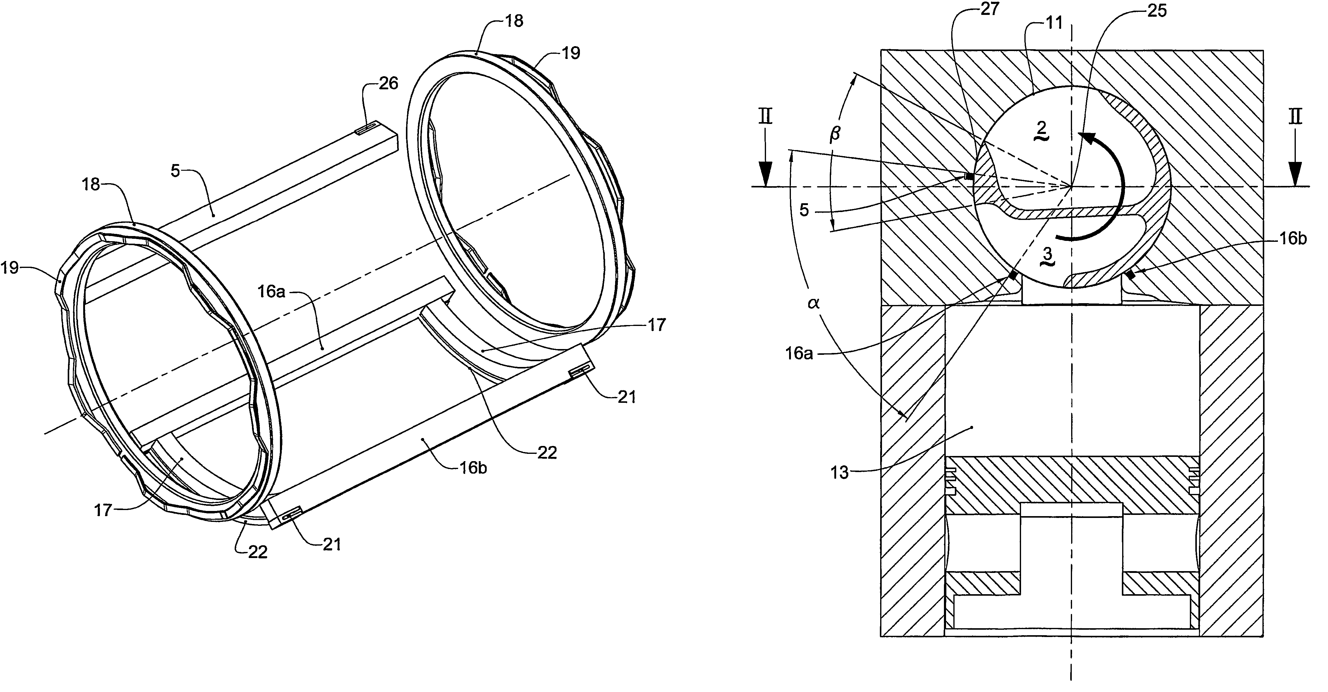
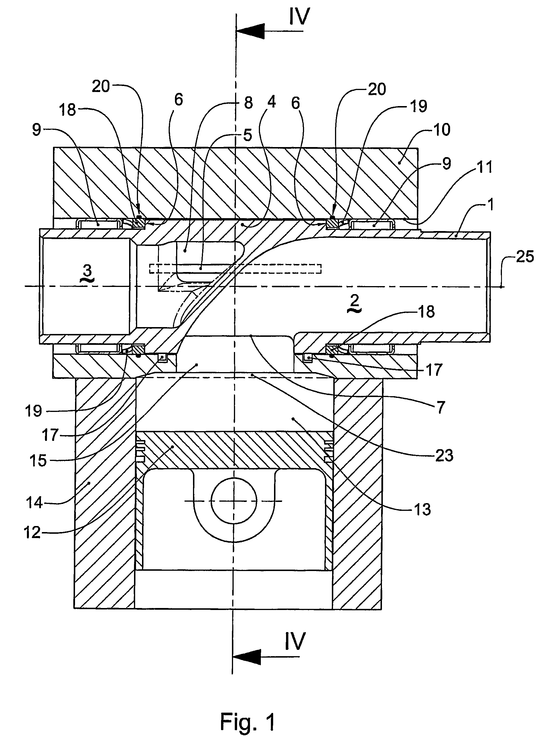
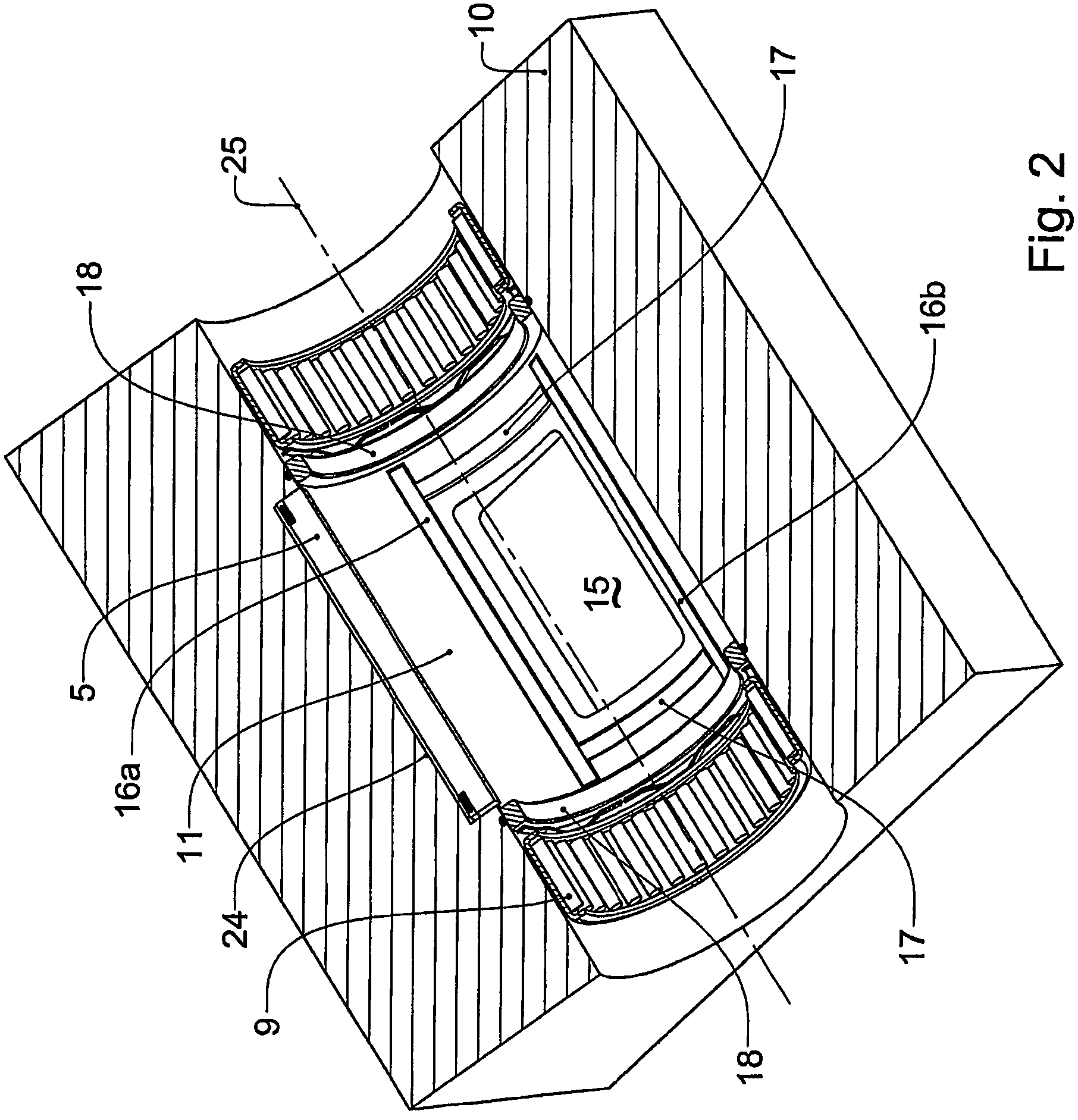
[0033]FIG. 1 depicts a rotary valve engine assembly comprising a valve 1 and a cylinder head 10. Valve 1 has an inlet port 2 and an exhaust port 3. Valve 1 has a cylindrical centre portion 4. Inlet port 2 terminates at inlet opening 7 in the periphery of centre portion 4. Exhaust port 3 terminates at exhaust opening 8 in the periphery of centre portion 4. Exhaust opening 8 axially overlaps inlet opening 7 and is circumferentially offset to inlet opening 7. Valve 1 is supported by bearings 9 to rotate about axis 25 in cylinder head 10. Bearings 9 allow valve 1 to rotate about axis 25 whilst maintaining a small running clearance between centre portion 4 and bore 11 of cylinder head 10.

[0034]The centre portion 4 of valve 1 extends axially a small distance past the axial extremities of an array of floating seals that perform the gas sealing function. Valve 1 steps radially inward either side of centre portion 4 forming a radial face. These radial faces forms valve seats 6 against which ...


PUM


Abstract

An axial flow rotary valve (1) for an internal combustion engine comprising a cylinder head (10) having a bore in which an axial flow rotary valve (1) rotates. The valve having a cylindrical centre portion (4), and an inlet and an exhaust port (2, 3) terminating as openings (7, 8) in the centre portion, the openings periodically communicating with a combustion chamber (23) through a window (15) in the bore. The clearance between the centre portion and the bore being sealed by an array of floating seals comprising at least two axial seals (16a, 16b) spaced apart on opposite sides of the window. The assembly further comprising at least one floating axially extending masking seal (5) being disposed outside the window and circumferentially remote from the axial seals.

Description

TECHNICAL FIELD[0001]The present invention relates to a port sealing arrangement for a rotary valve assembly used in an internal combustion engine. In particular the port sealing arrangement is applicable to axial flow rotary valves that accommodate an inlet and an exhaust port in the same valve terminating as openings in the valve's periphery and run with small clearance to the bore in which the valve is housed.BACKGROUND[0002]During rotation of an axial flow rotary valve, openings in the periphery of the valve are arranged to periodically communicate with a similar window in the bore of the cylinder head that opens directly into the combustion chamber. Alignment between the openings and the window allows the passage of gas from the valve to the combustion chamber or vice versa. During a portion of the cycle when compression and combustion of gases takes place, the periphery of the valve blocks the window. The gas sealing system prevents the escape of high pressure gas during this ...

Claims


Application Information

Patent Timeline
Patent Type & Authority Patents(United States)
IPC IPC(8): F01L7/16
CPCF01L7/021F01L7/16F01L7/023
Inventor WALLIS, ANTHONY BRUCETHOMAS, ANDREW DONALD
Owner BISHOP INNOVATION PTY LTD
Features
  • R&D
  • Intellectual Property
  • Life Sciences
  • Materials
  • Tech Scout
  • Unparalleled Data Quality
  • Higher Quality Content
  • 60% Fewer Hallucinations
Learn More