Supercharge Your Innovation With Domain-Expert AI Agents!

Pointer illuminator

a pointer and illuminator technology, applied in the field of pointer illuminator, can solve the problems of high cost, large light loss, cost increase, etc., and achieve the effect of reducing the light loss at the reflecting surface of the pointer and high brightness

Inactive Publication Date: 2009-12-01
YAZAKI CORP
View PDF14 Cites 10 Cited by
  • Summary
  • Abstract
  • Description
  • Claims
  • Application Information

AI Technical Summary

Benefits of technology

The design significantly reduces light loss at the reflecting surfaces, allowing for high-brightness illumination of the pointer across its entire rotation range with fewer light sources, thereby improving visibility and design aesthetics while maintaining efficiency.

Problems solved by technology

That means a great deal of light loss.
Therefore, in such a case, many light sources 2 are required in order to cover the whole rotation range of the pointer 3, causing cost up.
However, it also causes cost up.
However, such a purpose is hardly realized with the construction disclosed in Japanese Patent Application Laid-Open No. 2004-294344, that is, good visibility or good design cannot be realized therewith.

Method used


Image

  • Pointer illuminator
  • Pointer illuminator
  • Pointer illuminator

Examples


first preferred embodiment

[0059]In the following, a pointer illuminator according to the first preferred embodiment of the present invention will be explained with reference to the attached drawings.

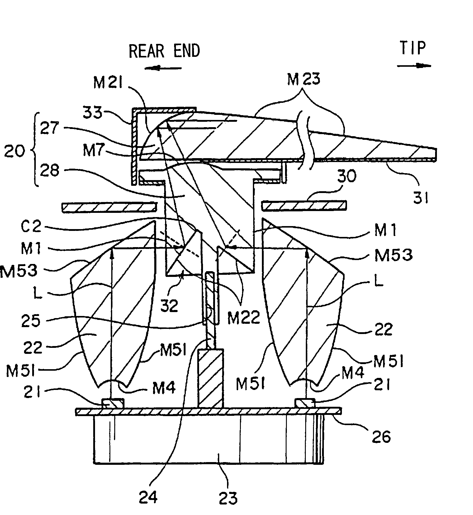
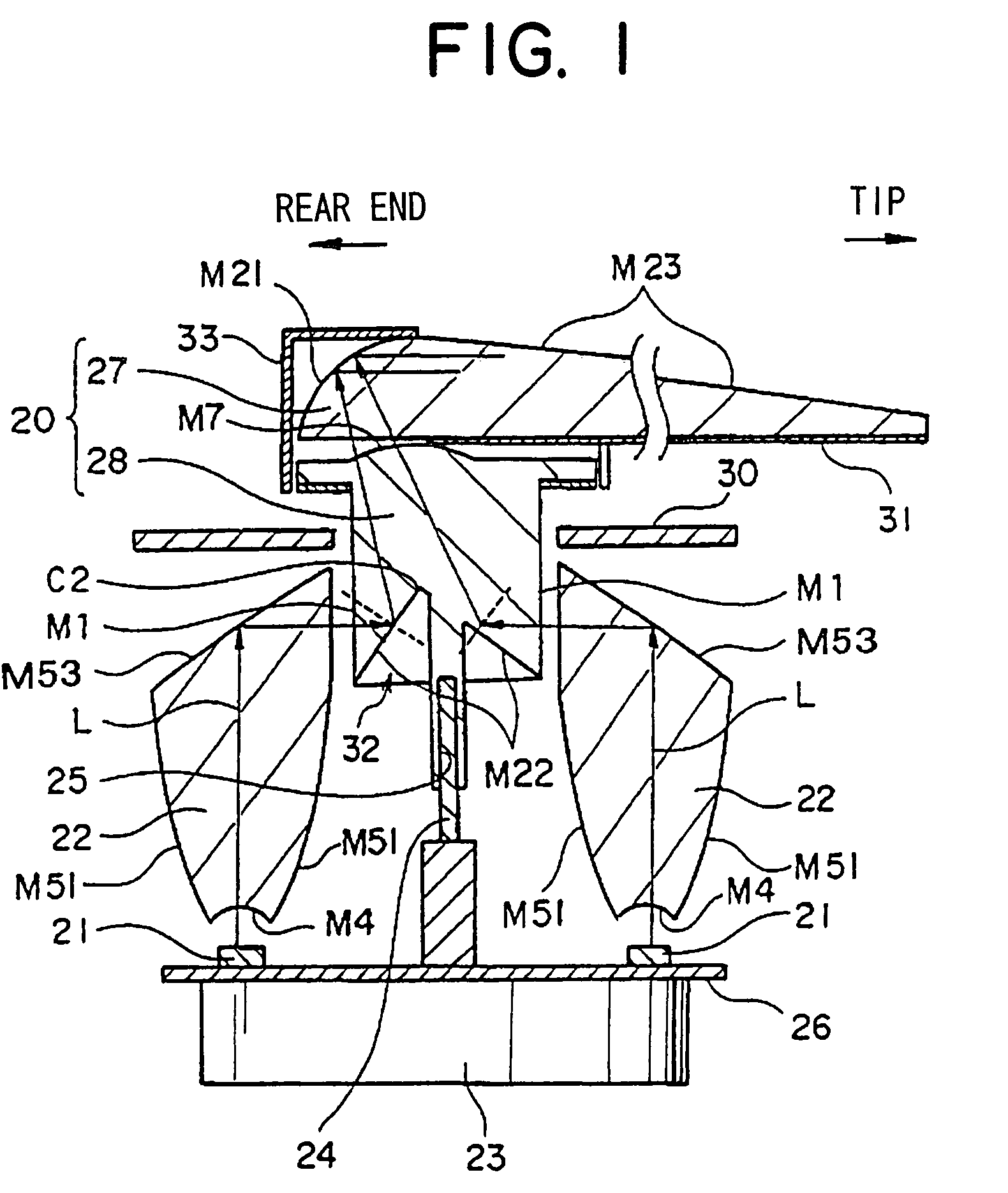
[0060]As shown in the figures, the pointer illuminator includes a pointer member 20, light source 21, and light-guiding member 22. The pointer member 20 is made of optically transparent resin such as transparent poly methyl methacrylate (PMMA) and transparent poly carbonate (PC). The pointer member 20 is provided with a bearing part 25 to which a drive shaft 24 of a motor 23 is attached and rotates around the drive shaft 24. The motor 23 is provided on the rear side of a meter board 26. The drive shaft 24 of the motor 23 is provided projecting toward the front side of the meter board 26.

[0061]The pointer member 20 includes a first reflecting surface M21 for a pointer and a second reflecting surface M22 for a pointer, which reflect light L incident (i.e. entered) on a surface M1 of incidence so as to guide the lig...

second preferred embodiment

[0102]In the following, a pointer illuminator according to the second preferred embodiment of the present invention will be explained with reference to the attached drawings. As shown in FIG. 11, the pointer illuminator includes a pointer member 20, light source 21, and light-guiding member 22.

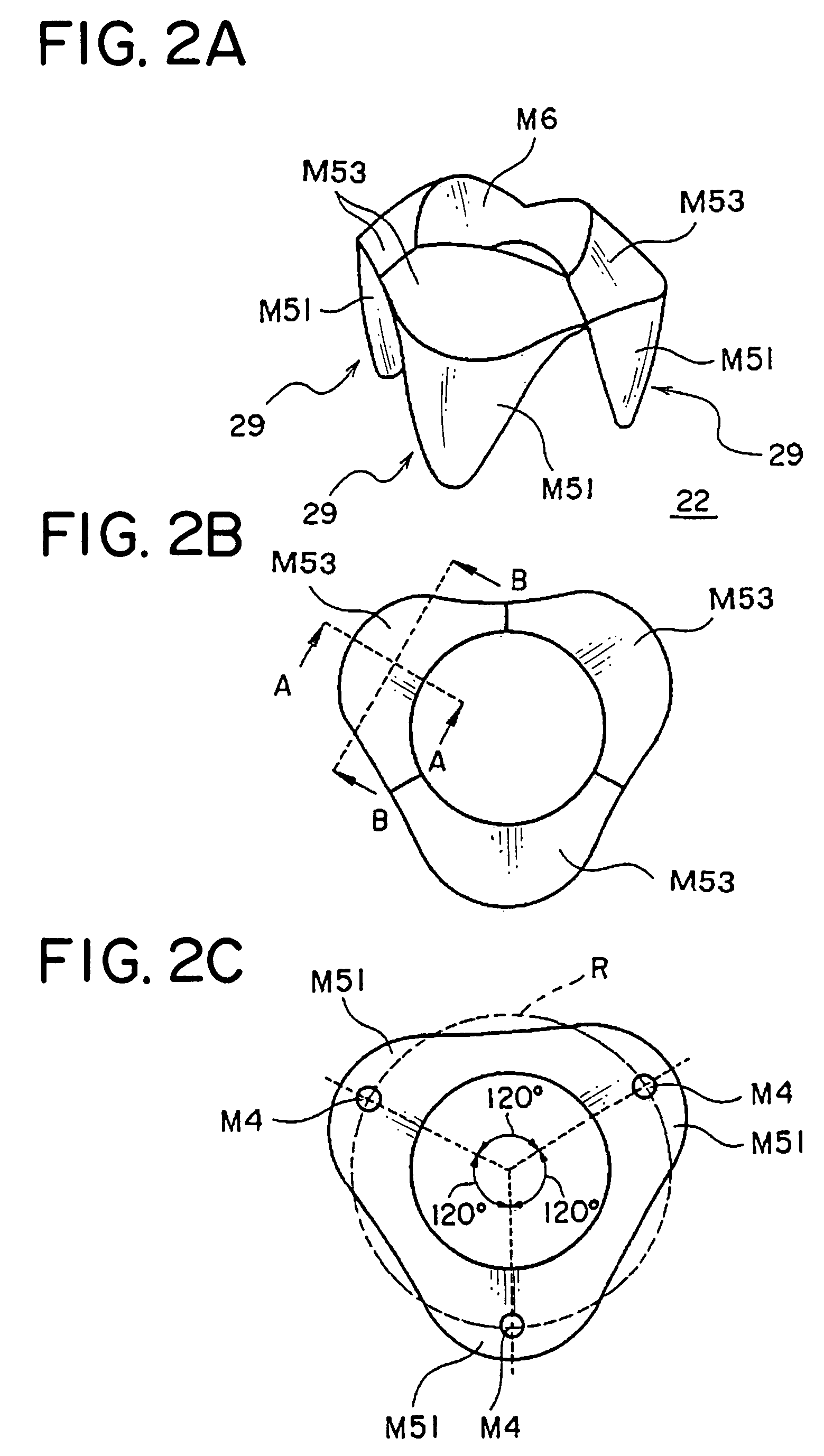
[0103]As shown in FIGS. 12A-12C, the light-guiding member 22 is formed approximately in a cylindrical shape in such a manner that a diameter thereof increases as approaching the light source 21. The light-guiding member 22 includes a surface M4 of incidence, first light-guiding reflecting surface M51 provided on the side of a drive shaft 24, second light-guiding reflecting surface M52 provided on the side situated away from the drive shaft 24, and surface M6 of outgoing. The surface M4 of incidence is arranged facing a light source 21 and provided on a flat surface, which is perpendicular to a center axis C1 of the light source 21.

[0104]The second light-guiding reflecting surface M52 is provid...


PUM


Abstract

The pointer illuminator includes: an optically transparent pointer member having a reflecting surface for a pointer, which surface reflects, light incident on a predetermined surface of incidence and guides the light to a tip of the pointer; a light source arranged around a drive shaft of the pointer member; and an optically transparent light-guiding member, which guides light from the light source to the surface of incidence and includes a first light-guiding reflecting surface provided on a face of the light-guiding member, an angle which the face forms with a center axis of the light source becoming smaller as the face leaves the light source so that the first light-guiding reflecting surface reflects the light from the light source to convert the light into approximately parallel light rays, whereby the light-guiding member guides the parallel light rays to the surface of incidence.

Description

BACKGROUND OF THE INVENTION[0001](1) Field of the Invention[0002]The present invention relates to a pointer illuminator, more particularly, to pointer illuminator including: an optically transparent pointer member having a reflecting surface for a pointer, which surface reflects light incident on a predetermined surface of incidence and guides the light to a tip (i.e. front end) of the pointer; a light source arranged around a drive shaft of the pointer member; and an optically transparent light-guiding member which guides light from the light source to the surface of incidence of the pointer member.[0003](2) Description of the Related Art[0004]Currently, a pointer of a meter for a motor vehicle has an illuminating function to ensure good visibility when a meter having an illuminating function at night or a selfluminous meter is being used in the nighttime and in the daytime. As shown in FIG. 16, light L from a light source 2 (valve, LED) placed on a meter board 1 is introduced into...

Claims


Application Information

Patent Timeline
Patent Type & Authority Patents(United States)
IPC IPC(8): G01D13/22G01D11/28
CPCG01D13/265Y10S116/06B60K2360/6985B60K2360/6992
Inventor HARADA, TAKESHIFURUYA, YOSHIYUKI
Owner YAZAKI CORP
Features
  • R&D
  • Intellectual Property
  • Life Sciences
  • Materials
  • Tech Scout
  • Unparalleled Data Quality
  • Higher Quality Content
  • 60% Fewer Hallucinations
Learn More